Starting the next generation Fitbit Cheat-O-Matic, but changing the name, switching to proper high-end bearings, and make a sturdier base and cam follower mechanism. Should be slick if everything fits nicely and plays nicely.
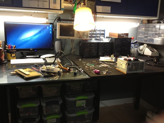
I guess I forgot to post an update to the update of my workbench. Not only did I clean up the gigantic mess that had accumulated on it, I improved the lighting and workspace availability:
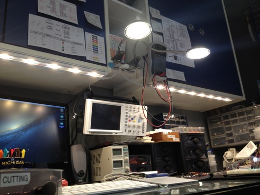
Prior to this upgrade, I had fluorescent lighting under the blue cabinets over the bench. They extended down about 3 to 4 inches and kinda got in the way. I also didn't think through the placement, so they were back about half-way under the cabinets. This meant they didn't put light out on the front edge of the tabletop like I would have hoped. Here's the old lighting:
The monitor on the left barely fit behind the light and the light extended down lower than the top of the monitor. Dumb. I might have been drinking bourbon that day. Like, more than a shot or two. No matter. That is history. Today, we have wonderLEDs!
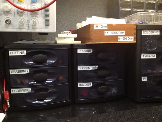
Also, notice I suspended my oscilloscope above the desktop. It freed up quite a bit of desktop space. I added some more plastic storage drawers to organize my tools and miscellaneous other parts that usually wound up spilled all over the work mat. I labeled the drawers for quick searching and fun:
I believe I found those at Target. They were inexpensive and they work very well. They have little rubber footies to keep them from sliding around on the glass tabletop when opening and closing the drawers. As you can see, it's easy to tell what's in each drawer... If you're me. My wife needed a few seconds to interpret the labels in order to find the scissors. Scissors cut things. They're for, "cutting." BOOM! Easy-peasy lemon squeezy.
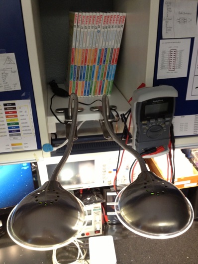
I picked up the two LED bars under the cabinets and the two gooseneck LED lamps at Lowe's (maybe Home Depot, can't remember). All told, I maybe spent $100. The best thing about the bars is that they're quite flat, leaving plenty of headroom for monitors and whatnot. The two flexible lamps clamp onto the little shelves I built between the cabinets:
These are about $20 each. They put off great light, stay cool and I can point them individually to light a component any way I like.
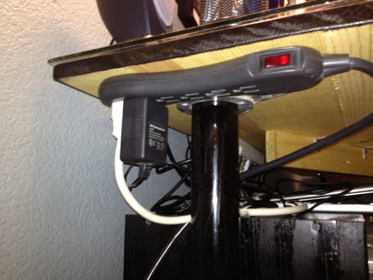
I set up the power to go through a single multi-outlet toward the back and under the ledge of the workbench table top (please excuse the fuzzy photo):
It's an easy reach to turn the lights on and off. The two gooseneck lamps have their own switches on the shelf above, so it's easy to switch them on or off without taking down all the lights.
EDITOR'S NOTE: I've attached PDF files of the pentagon PCB and the motherboard PCB. If I had time to label them and make them pretty, I would, but this was never designed for mass production or consumption. Use at your own risk and frustration.
For those with a short attention span, I give you a photo of the completed project (my biggest to date):
If you're interested in the story of this things, continue reading...
This idea came about randomly as a gift idea for my wife. I've built useless machines, clocks, etc. for other people (and myself), but hadn't built anything for my wife. I'm not sure what she's going to do with this thing, but it's the thought that counts.
Initially, this was just going to be a small little desktop thing with a few RGB LEDs on a circuit board with some kinda diffuser. Nothing fancy. Then, while walking through Home Depot, I found a frosted glass globe replacement thing for a wall sconce or lamp or something. It looked cool, wasn't too large, and screamed to have a bunch of LEDs stuffed inside it. I was at Home Depot for something else, of course, but I bought the globe, anyway.
Next, I had to figure out how to illuminate the inside of this thing and make it do more than just cycle through colors. The first thing I did was devise a plane for the "bulb." I decided to go with a dodecagon, which I believe means a 12-sided object. Actually, I had no idea what one of these things was called. I just figured that I needed pentagons to make something more globe-like than a cube. I wanted light to emanate outward from this bulb thing like a light bulb, but with as few sides as possible. The sides were no doubt going to be PCBs, so the less complex, the better. Not that this wasn't one of the most complex circuit boards I've ever built in my short time as a hobbyist circuit builder. Here is the paper prototype:
I'm a visual guy, so I wanted to see this thing in real life and also make sure that it would fit into the opening of the frosted glass globe thing I bought. It did fit. I could handle pentagon-shaped circuit boards. The plan seemed doable.
The next step was to plan out and print the pentagon LED panels for the bulb. As always, I use Adobe Illustrator to design the traces on my PCBs. I don't know if I've mentioned this in other posts, but I tend to lay the components for a project on the flatbed scanner and scan them in, then place them in Illustrator so that I have exact placements for through-holes and spacing on my homemade PCBs. So far, that idea has worked out swimmingly. The planning of a PCB in Illustrator looks like these next photos:
After I get the positions of the LED packages on the PCB, I need to connect them together and to ground, which on these panels were the edges, since they'd all be tied together at their corners. In hind sight, I would have gone the route of a common anode, not a common cathode. It would have been easier to control the individual colors with a simple N-channel MOSFET, as we'll see in a little bit.
Like I did on the LED Reading Lamp project (so far, anway), I just worked out the best routes for the traces that would allow the three different colors to be connected in series. Since the red LEDs dropped less voltage than the greens and blues, all six red LEDs were able to be connected in series with a single 1 ohm resistor. The green and blue LEDs dropped enough voltage that I needed to break them up into sections of three LEDs, which meant a total of five series circuits on each panel. My sketch to figure this out looked like this:
When the circuits were all tied together and the microcontroller and all other parts were together, the ammeter showed a maximum draw of only 270 mA. If it were for the 12 volts that drive the panels, I probably could have run this off a USB port. Oh, well. Back to our story... Here is the final trace design, including the location of the limiting resistors on the back side of the PCBs:
The blue resistor outlines show me where I need to place resistors on the back side of the panels. There are also two jumper wires for spanning out the second green and blue series circuits. I did that because I'm lazy and want to simply solder a 5-pin header through the back of the board. I can't fully explain why, at this juncture. It might have been late and I was tired. Who knows?
Finally, I duplicated the pentagon PCB design five more times and laid them all out so that I could print them together and use a band saw to cut them apart. The gap between the edges is enough for a band saw blade with a hair to spare for sanding and clean-up.
As always, I used the toner transfer method to print and etch the boards.
If you count the holes and the pads, I had a lot of soldering to do. A completed panel took me about 15 minutes, if my work area was prepped and the soldering iron was ready.
I don't know how ingenious this was, but after the Iron Man arc reactor thing, I needed a more efficient method of soldering SMD parts. My hands aren't steady enough to not flip the little parts off the board when the tip of the iron approaches. I stumbled onto poster gum at the grocery store and a light bulb went on. A super-tiny little ball of sticky poster hanging gum holds the part in-place perfectly and is non-conducting, so it becomes a permanent part of the board, but who cares? The solder looks 2.4 million times better than if I put a weight on the part or I just carefully attempt to get one leg soldered as an anchor.
Here is what the back side of a panel looks like:
On the back, there is a 5-pin header, a single 1-ohm resistor for the red LEDs, and four 120-ohm resistors for each of the sets of green and blue LED circuits. The original thought behind the header pins was that I'd have lots and lots of time to make really nifty plug-in wires for the various panels and they's all converge on the motherboard of this thing for easy modular construction. That was dumb and painful. So I went the cheap and fast route and soldered wires all over the underside of the complete bulb and had just three wires come out for each color, plus a ground wire. Way easier, although soldering all those little wires was a royal pain.
One of these panels by itself was stupidly bright, so imagine what six were going to do:
With all of the pentagon LED panels built, I had to "stitch" them together by their edges to bring all of their ground lines together. Here is a sort of sequence of the bulb being built:
I used bare copper wire to stitch the corners of the panels together. The extra wire was snipped off, of course.
With all the panels stitched together, I had to connect together the color pins from each of them so that I'd have only one wire for each color coming out of the bottom. But, before I did that, I had to see this thing lit up on the breadboard. So, I created, "Squiddy" the LED bulb:
Lit up, Squiddy looked like this (which was toned down so that the iPhone 4's camera wouldn't freak out):
The bulb is powered with 12 volts, but controlled by pulse-width modulation via the Atmel ATmega168 microcontroller. A potentiometer controls the dimming of the LEDs. The other knob on the breadboard is a rotary encoder. This allows the user to change the mode of the lamp from a plain white for reading to an auto-cycling rainbow of colors to a user-selectable color. The built-in pushbutton changes the mode. The rotary encoder's knob changes the speed of the auto-cycling colors or the user-selected color.
Here is a shot I took with my Canon 20D so that a photo could actually pick up the red, green and blue LEDs in the LED packages on the panels (which turned out to be a really cool artsy photo, to boot):
After all that, it seemed like this wasn't that large of an undertaking. Then I realized I hadn't even designed the motherboard OR the case. So, back to Illustrator to design the ROUND motherboard.
As always and as mentioned above, I scan the parts in and put them in the Illustrator document to be sure I get perfect alignment for everything. Yes, the datasheets have great specs for size and positions of pins and such, but I like seeing the parts next to each other on the screen in front of me. I usually put backside items in faint blue so I know where to put the through-holes to the front. This contraption is designed to run off a wall wart power supply, so it can MAYBE go a low as 12 volts (although my testing shows it prefers more) and as high as about 18 or so. 15 volts seems to be the magic number for many of the orphaned wall warts I have in my box-o-wall-warts. The diameter of the the board is about 5 mm shy of the opening of the frosted glass globe. The four screw holes were meant for stand-offs, but I wound up hot gluing a couple of little boards to the bottom of the PCB like table legs because I was antsy to finish it. Nobody see, nobody knows [click click].
Toner transfer method means laser printing a reverse image of the traces onto shiny blue model decal-like paper and then heating that face down onto super-clean copper PCBs and then soaking in water until the paper lifts off to leave the toner on the copper:
It look AWESOME at this point, because I've started to run the paper and the copper board through the laminator FOUR times. I'm still getting a little pitting in the final etch, but the traces are generally plenty good for my projects. I'm considering trying the photoresist method to see if I can get higher quality edges on my traces.
Etched and drilled, this baby's ready for parts.
An LM7812 12-volt voltage regulator, an LM7805 5-volt voltage regulator, a couple of capacitors, an ATmega168, and an inductor, so far. With the rest of the parts and a few wires to suspend the bulb above the main board, the final main assembly looks like this:
Again, I felt good having completed this much work on the lamp. That good feeling didn't last long when I realized I had no concept for a case or buttons or anything else. Think, think, think... Ding! Into the garage!
Some poplar, a little router action, a pinch of band saw, and BAM! Rough case:
The top piece of wood has a hole with a routed edge that will "grip" the flange on the glass globe. At the back of the lower piece of wood, I've notched out a place for the power plug and the power switch. The knobs were cut off a poplar dowel I had, for what I have no idea. Put together, the rough body of the case looked like this:
The stained/finished gripper groove looks like this:
A test run of the fitting of all the parts and the case:
The knobs were just sitting on the front of the case. The main circuit assembly was kinda hovering in the opening. I had already hot glued the switch and power port into their respective slots. For added stability and wear protection, the power port was super glued, as well.
As for the final shape of the case, I used the band saw to round the corners. The rest was belt sander city. I sanded the ever living crap out of that thing to get all the sides and edges as smooth as possible. I use this 3X 320 grit stuff that really puts a fine finish on the wood prior to staining. The stain is the same stuff I used on the UME Mark II machines (Useless Machine Ever). It's a combination of stain and varnish that makes it really easy to put a nice color and shine on a finished wood product.
The interior of the case was routed out to allow the wires to go from the switches and knobs to the circuits:
The rotary encoder and the potentiometer were hot glued to beat the band. I'm medium-confident that they will not leave their posts.
I cut out a little ring of felt to cushion the glass globe in its hole in the case. I don't know if it was necessary or if it will provide any protection, since we're dealing with a wooden case. Not like it's glass on steel or something. Eh, whatever. Looks swanky.
Next step: Wire up the controls to the main circuitry. I used strips from an IDE cable to keep it neat inside.
As I mentioned before, the main circuit board is standing on wood stilts held in place by hot glue. It's ugly, yes, but it's inside and it's plenty sturdy:
Here is a video of it functioning, albeit a little flaky, but good enough for government work:
For those of you with short attention spans, like me, here is a quick and lame video I threw together in iMovie:
I am building this for the new awesome bed I will be building this winter for our bedroom. There will be two of these lamps, one for me and one for my wife on either side of the headboard. The LED head will have a metal (or whatever I end up finding) shroud on it to keep light pollution down to a dull roar for the other person who might be sleeping.
The previous post showed the traces for the printed circuit board I made. Here is a photo of the board with the six surface-mount triple-LED packages soldered into place:
Each of those white squares has three über-bright white LEDs in the yellow stuff. I designed the circuit board to connect one LED from each of three SMD packages at a time, thinking I might use that layout to better dim the whole lamp head. Turns out, that circuit layout just makes for a really cool-looking circuit board.
Here is a photo of the underside of the LED lamp head with the resistors for each set of three LEDs in series:
There are three holes left, as of that photo, which will have the ground wire connected through and soldered. Each set of three LEDs and their resistor will have 12 volts supplied to them which will be controlled by a 3904 PNP transistor which itself will be controlled by the AVR microcontroller. The transistor will act as a switch for the pulse-width modulation provided by the microcontroller.
For those who aren't sure what pulse-width modulation is, the short story is that it is super-fast on and off switching. It's fast enough that you do not see a flicker. We use PWM to dim LEDs because they do not work efficiently without a specific voltage being given to them. So, we flicker the voltage that the LED likes really fast and emulate dimming. For each "flicker" of the switch, the amount of time that flicker lasts can be divided between on and off. The more on time we give the LED, the brighter it looks. The more off time, the dimmer it looks. Weird, yes. But, that's the right way to do it. PWM also works for DC motors and such. Discussion for another time. Maybe that's a discussion for someone who was properly trained in all this. I know enough to be dangerous, even though I try to be safe at all time.
The cable carries six +12VDC wires and two ground wires to the back of the LED lamp head. The other end is currently plugged into the breadboard prototype of the controlling circuit. Here is the breadboard and labels for the various parts:
The power for the whole shindig is provided by a spare "wall wart" power supply, like the ones that power your TV boxes or network routers or wireless home telephone base stations. Here is the actual one I'm using, the end of which I snipped off to be able to plug its wires into my breadboard:
These silly things provide pretty craptastic power, as far as DC circuits are concerned. They pretty much always supply a voltage other than what the label reads. This particular one measure out at 15 volts. Voltage to spare, baby! What's important is how much power (amps) we need to draw from the thing. Our circuit cannot pull more milliamps from the adapter than it is labeled to be able to supply. Luckily for this little project, we're only drawing at maximum about 91 milliamps. Not much at all, considering we're powering 18 super-bright LEDs and a little computer-on-a-chip. The Radio Shack adapter I'm using provides up to 500 mA of current. We're good.
The Atmel AVR microcontroller (the model is an ATmega328P, which is complete overkill for this, yes, but I didn't feel like reconfiguring my customized Arduino IDE to work with one of my little 8-pin ATtiny chips) basically sits and waits for the pushbutton to be pressed. When it senses a press, it delays for 25 milliseconds to keep the switch from bouncing on and off (a thing called, "switch bounce"), then gradually fades the LEDs up to the next brightness level. When it hits the last level, the next button press will shut off the LEDs.
OK, I am not making one of these and I did not make this one, but I consider this to be super-swanky and a must-show-off piece in my collection of strange old things.
I inherited this from my grandmother who passed away around Christmas of 2009. It's plastic, but my grandparents purchased it for-real in Hong Kong when they lived over there. It's dirt-old and reminds me of the leg lamp from the movie A Christmas Story. When my parents brought it down to me and my wife saw it, all I could say was, "It's frah-jee-lay." It's awesome is what it is.
This will be the first thing filed under, "Swank-n-Funk."
I'm building a bright LED reading light that will be powered by a "9V" wall wart power supply and will use a flexible stem to position the light to not disturb my wife while I read and she sleeps.