Starting the next generation Fitbit Cheat-O-Matic, but changing the name, switching to proper high-end bearings, and make a sturdier base and cam follower mechanism. Should be slick if everything fits nicely and plays nicely.
I built a machine to walk my FitBit for me. I call it the FitBit Cheat-O-Matic! Why? Our office is having a FitBit competition this month (November 2013). In preparing for the competition I overworked my Achilles tendon and could not participate. So, I adopted the mantra:
If you can't join 'em, beat 'em.
The FitBit Cheat-O-Matic is a machine that shakes my FitBit for me 24 hours a day, 7 days a week and does it faster than my normal walking pace. I suppose it's actually faster than most people can run, for that matter. Sure it's cheating! Not only is it cheating, but it's cheating at a level that's so blatant it can't be mistaken for anything else! It's fully disqualified from the competition, of course. But the point is no longer to win the competition, but to be totally ridiculous and to rack up outrageous FitBit stats and make people laugh or maybe shake their heads.
How many times has this happened to you? You have a little LED project with an AVR ATmega328 microcontroller (or Arduino) at its core and you need to light up a boatload.... A dingyload of LEDs. Maybe it doesn't happen a lot to you. It's happened on three recent projects for me. My latest two LED projects are a timekeeping piece that illuminates 21 characters from behind and a simple LED chaser thing.
As usual I wanted to keep the component count down on these projects. I also tend to prefer not to use a ton of ICs with busses between them and whatnot, if I can help it. So much darn soldering and stuff. Meh. Luckily, back in 1995, so the Wikipedia story goes, a super-smart dood named Charlie Allen at Maxim Integrated devised a super-ingenius way to control a large number of LEDs using a not-so-large number of microcontroller pins. The method is called, "Charlieplexing" and it seems a but daunting, at first, but it's not that bad once you figger it out.
I believe I've mentioned it before: I work at an amazing web and software development shop called, "meltmedia." We have a gaggle of highly talented software engineers, web developers and designers. Sometime back in 2011, meltmedia was in search of a new tag line to kick off a for-real live marketing campaign. Marketing was something melt hadn't worried about before then.
While in San Francisco at the 2011 Apple World Wide Developer Conference, in a bourbon-fueled barrage of submissions to the company's on-line suggestion box for new company tag lines, I came up with, "We are Interactive Superheroes." It stuck and I won a $90 bottle of bourbon. Woohoo! To be clear, I am fueled by many things: Caffeine, sugar, soda, etc., not just bourbon. I like chocolate milk. I happen to be a major bourbon geek and had been sampling fine bourbons at a speakeasy in San Francisco called, "Bourbon & Branch" before I went back to the hotel and started submitting dozens of mostly silly ideas for meltmedia's new tag line.
For the short attention span version of this, here is a photo of the three partners of meltmedia in their full costumes with their props:
We'll start with the biggest prop: Mike's Techno HAMMER (Highly Active Mike Moulton Energy Repeater). I needed this thing to be big. I didn't have much time for any of these props, especially the HAMMER. To sturdy up the thing and to keep it as lightweight as possible, I started with green foam from Michael's:
The handle is a piece of PVC pipe from my pool equipment upgrade last year. I knew I'd eventually find a use for the pipe!
At first, I wasn't going to get all electronicky on this thing, but it just didn't seem right to have a TECHNO HAMMER without random blinking LEDs on recycled circuit boards, so, this thing needed a circuit to make random LEDs blink. It also needed a way for Mike to turn on and off the LEDs at will. I did this by embedding a standard pushbutton in the handle:
I cut a hole for the button, then cut a BIG hole behind it to allow me access for glueing. To be sure the button would be at least somewhat difficult to push through the handle, I jammed a piece of leftover green foam into the handle and behind the button before I closed up the back of the handle:
To crappily simulate leather wrapping on the handle, you can see in the image above that I took strips of Gorilla® tape and folded one edge, then wrapped up the handle at an angle. It kinda did the trick. Ya do what ya can in the time ya have, ya know?
The button was in between the batteries and the LED blinking circuit. A simple momentary power-on functionality. The circuit was an Atmel® ATmega328 AVR® microcontroller (same one used in certain models of the Arduino). It was programmed to strobe the LEDs (rifle through each of them and turn them on or off many times per second, like a TV scanline). To keep the current draw to a minimum (to prevent the AVR from cooking), I had all of the LEDs cathodes return to ground through a dinky little constant current devices (CCD) from ON Semiconductor (part number NSI45020T1G). There are 12 LEDs. 12 pins on the AVR are randomly set to be on during their time slice or off. The little CCD kept the current to 20 mA for each LED. This allowed me to use red, green, yellow, and orange LEDs, regardless of their required forward voltage, since the current was always 20 mA, which they all liked. The other reason for doing it this way instead of a resistor was power consumption: The CCD is way more efficient that a resistor that dissipates heat to get the current to where it should be. The circuit was powered by two little AAA cells, so the voltage was about 3 volts DC. Since the microcontroller drew very little power and the LEDs were only on one-at-a-time, the batteries should last for days and days if left on continuously. I did run a test and they stayed lit for about 4 days before I had to assemble the HAMMER circuit. Here's the circuit and batteries:
And here is the ugly underbelly of the circuit (again, time was not on my side, therefore beauty was not on the HAMMER's side):
The next part of the LED circuit is the 12 LEDs that poked through the recycled circuit boards (I'll get to the boards shortly). I drilled holes in old boards pulled from an old (and quite large) oscilloscope that was given to me but that did not function. Each LED was given its own wires and a nice heat-shrink tubing treatment:
Two fairly similar old circuit boards were used for the two sides of the HAMMER. I drilled appropriately sized holes in kinda-random places and poked the LEDs through and grouped the wires together, connecting the grounds together:
Each side's wire bundle would go through little holes in the foam core of the HAMMER and into a secret compartment that held the circuit main board and the batteries:
The compartment was crudely cut (like most of this sad but fun project) into the foam core:
The LEDs looked right at home in the old PCBs:
The shell of the HAMMER was just cardboard faces stuck together hideously and hurriedly with Gorilla® tape. The cardboard was coerced into shape around the foam core:
The entire thing was eventually covered in Gorilla® tape:
Next came the primer and silver metallicish paint for the shell. Turns out, Gorilla® tape doesn't take primer as well as I had hoped. But, it was good enough for the intended limited use:
In the image above, you can see the circuit/battery compartment door and the makeshifty little riveted Velcro® closer... Thing:
Yes, it's cheesy and not at all indicative of a quality or sturdy product, but, again it serves its purpose well enough. Here's what all the crap looked like crammed into the compartment:
Finally, I soldered all 14 of the LED leads to the circuit board and connected the batteries and pushbutton and it was ready to go!
The photo doesn't show it randomly lighting LEDs, of course, so here's a video of the LEDs in action:
And finally, here is Mike actually being an Interactive Superhero with his Techno HAMMER:
At the office, we decided we were going to have a stocking decorating contest for Christmas. The rules were pretty lax, so I immediately thought of interactivity and electronics and blinky lights and whatnot. Well, that, and there was no way in you-know-what that I was going to hot glue glitter and spongy letters to a stocking with electricity being involved.
Here is a video of the final product to pique your interest:
How did I do it? Easy. Some AVR programming (through my usual Arduino hackery) and some simple electronics and BOOYAH! Motion activated stocking with a Santa sign and some jingle bells.
First step was to make a framework to hold the mechanics and the electronics. I used plexiglass and Lexan to support the pop-up Santa sign and to act as the general body of the mechanical works inside the stocking. The layers of plastic were riveted together.
To push out the stocking into shape to make room for the guts, I took extra heavy gauge copper wire I had in my electrical drawer and used pieces of that for "ribs."
The sign was pushed up out of the stocking with a regular hobby servo and some armature work. The plastic worked as a track to keep in straight and sliding smoothly. The armature was made from parts used in RC airplanes I got at a hobby store.
The next thing was to make it motion sensitive. That was initially going to be controller by a PIR sensor, but it turned out to be too whacky. I settled on a nice little sensor by Sharp that I picked up at Sparkfun.com. They simply alter a voltage depending upon what's in front of the sensor and how far away it is. Really simple to experiment with and get a good idea of what numbers to expect from the ADC to trigger the action.
I tried a number of methods for jingling bells. The first was funny, but a bit difficult to implement on the sticking itself. It involved a wheel (or plastic gear, in this case) and a rod with the bells hanging off of it. The idea was that the motor would push and pull the bells rapidly and make them jingle. It worked on the bench, but not in the stocking.
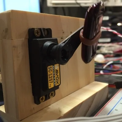
The ultimate solution I stuck with was simply a cam on a motor behind the bells. When it ran, it smacked the back of the front face of the stocking where the bells were hanging. It was essentially a big honking 12V phone vibration motor.
Wood cam that vibrates jingle bells
Next step: Jingle bells. I tied them to the cheap Chinese-made stocking with thin copper wire as a sort of twisty-tie thing. Worked great. I wasn't very organized about where I put bells, just wanted to get a bunch in the general vicinity of the bell thwacker motor.
The brains behind all of this is, as usual, an AVR microcontroller. I use my own version of the Arduino IDE to upload firmware to my AVRs on the breadboard. The code is super simple. It basically just waits in a loop for the ADC to show a value from the IR sensor that meets whatever threshold I figgered out in my experiments with the sensor and ideal distances for triggering the sticking. When it gets a hit, it turns on the MOSFETs for the servo (the sign) and the motor (the bells). It start the motor spinning for hitting the bells and pushes up the sign. After a few alternating blinks of the [not-added-at-this-time] LEDs, it retracts the sign and stops the motor and cuts power to them both. That's pretty much it. Here's the RoboStocking motherboard:
I even put holly on the board in the etch. :) Because the wall wart that powers this thing outputs about 20VDC, I put a LM7805 5-volt regulator on the board for the logic stuff and another LM7805 regulator for the motor and servo. There was no reason to run the motor at its full 12 volts. It was only smacking the back of the stocking. There are two regulators because the power draw of the circuitry plus the motor plus the servo was causing the AVR to shutdown. Running on their own circuits gives them each the full power available through the individual regulators.
As always, I drew the circuit board in Adobe Illustrator, flipped it and printed it on my Samsung black and white laser. I've found that running the transfer paper through the laminator four times makes the toner really adhere to the copper without problems. I've notice that after four times, when you drop the board with the transfer paper stuck to it into the water bath, it dissolves off the board pretty quickly. The etch afterward is much higher precision, as well.
The only thing left was to draw a cute sign for the slide-up. It took me a bit of trial and error, but I finally drew a decent cartoon Santa in my normal style and slapped a Christmassy looking font in the sign part of the slide-up thing. This setup makes it look like Santa is just hanging out in the top of the stocking. When he slides up, the actual sign is revealed below him, as if he's pulling it up for you.
Santa sign on RoboStocking
With everything assembled, the guts of RoboStocking look pretty cool:
What makes this story funny is that I was not able to finish this silly thing in time for our company Christmas party. I had to put the final touches on it over the weekend and bring it in the Monday following the party. It was met with great reviews, but could not win the contest that had past. :( Oh, well. There's always next Christmas. Sound and lights will be added, I assure you. ;)
I was contacted by Element 14 (Newark.com) recently about doing some product test drives using some of the products from their line card. I took two to three seconds to think about it. I know, tough one...
I have been chomping at the bit to use ZigBee wireless technology in a project. Digi International makes some REALLY cool and easy-to-use ZigBee RF modules that bring ZigBee technology down to a level that even I can implement without more than a few terse passes at a wireless book and a couple of datasheets. So, the first piece of loot I requested from Element14 was an XBee S2 module. I would love to link you to this module at Newark.com, but it appears to be gone. That is sad. BAck to our story... There was a spending limit on my test-drive loot. I ordered one XBee S2 module on my tab. The other XBee module was sent to me courtesy of Element14.com.
The ultimate project is based on a need at our house: We hang out on the back patio quite a lot and when we invite guests over, even after we ask them to just come on in, they ring the doorbell and we can't hear it out on the back patio. The leave disappointed that we would not be home when we said we would be. I'm kidding. Usually they do walk right in.
The first drawring I made used a brass marine-type bell with a string that was routed from the front door around to the back patio. Guests could simply tug on the string to get our attention. My wife wasn't keen on the network of pulleys and string required to make that happen. The drawring above is the watered down, no-fun-havin' version. Awe, who are we kidding? It's still fun. It's ALL fun! What's not to love about electricity and radio frequency waves making things do stuff??
Plan B for the remote doorbell is much cooler and much more electronic: Rig XBee to the house doorbell system so that it can signal a solenoid type of thing to plink a brass bell on the back patio. Not as Wallace & Gromit as the pulleys and string, but still pretty darn cool.
Oh, let me get this out early: Yes, übernerd, I know that XBee is overkill for a simple remote doorbell. The final version of this thing will use a simple little OOK (on-off key) RF module pair that simply sends on or off (button pushed or not). For now, though, this is a great way to get to know Señor XBee and his amigos.
Before I go any deeper into this project, I want to HIGHLY recommend a book on the subject of AVR/Arduino microcontrollers and ZigBee networks. If you're interested in this stuff, go out and get a copy of Building Wireless Sensor Networks by Robert Faludi, published by O'Reilly. I also highly recommend you do NOT do what I did: Do not buy the book, read it cover-to-cover, and do absolutely nothing hands-on. I wound up having to re-read large portions of the book again to get my bearings with the XBee modules from Digi. Try to have an AVR microcontroller (or Arduino) and a couple of XBee modules on hand when you start reading the book.
Now, the first thing I have to say about these modules is that they are stupidly simple to setup and get running, as you'll see in this post. I was asked to do a write-up by Element14.com and this is an easy one: These are AWESOME. There are plenty of sources on the Web for connecting XBee modules. I won't go into major detail, but I will show you how quickly you can get to AVR microcontrollers talking wirelessly with two Digi International XBee S2 ZigBee RF modules. Keep reading...
The process for getting two XBee modules talking, or, in this case, two AVR microcontrollers talking via XBee modules, it this:
Get two XBee modules (Farnell.com part 1690810) and a handful of 10-pin, 2mm headers used to adapt the non-breadboard-friendly XBee pins to your breadboard
Build cheesy adapters for the XBee modules so that they fit your breadboards
Download the X-CTU Windows program to upload newer firmware and appropriate firmware to the XBee modules (this relates to setting up one XBee module as the "coordinator" and one as the "router" [see book above])
Put some serial-savvy code on an AVR chip or Arduino and connect its UART pins to one XBee module's DIN and DOUT pins
Connect the other XBee module's DIN and DOUT pins to a serial cable to your computer
Send commands through the air to the AVR from your favorite terminal program
OK, that's oversimplified, but if you're comfortable with building circuits and working with Arduino or AVRs, that's all there is to it. Take a look at this setup in action (and please forgive the hastily shot and edited video):
If you're a Mac person, and I know I am, you're going to disappointed in the lack of a Mac firmware updater for XBee modules. However, it is pretty darn simple to fire up Boot Camp or VMware and update the radios the way the aforementioned book suggests. I just picked up my breadboard with the two radios and the AVR and the USB-RS232 cable and plopped it on my desk next to my iMac and fired up VMware and did it. Nice and easy, save for one issue: Once the upload of the firmware was complete, Windows XP Pro went to a BSoD (Blue Screen of Death). Pretty awesome. Let me say that it is no secret that I hate Windows. I'm disappointed in Digi for note having a Mac client to update firmware on the XBee modules. Maybe someday...
If you follow the book, you can get two AVRs or a computer and an AVR communicating in pretty short order. The code I wrote for the AVR to receive the serial commands from the computer to switch the traffic LEDs was easy and it actually worked the first time. It's really cool when stuff works as advertised.
If you've got some communicating you need to do between your microcontrollers, especially multipoint stuff, XBee modules are the way to go. Soooooo easy to setup and use. Head over to Newark.com or your favorite source for Digi International products and start mesh networking your DIY gadgets.
This post was originally about the remote doorbell idea. I'll write a separate post about that completed project using simpler RF modules from SparkFun, as ZigBee is WAY overkill for a remote doorbell, unless you're putting little remote bells or buzzers all over your mansion.
Well, we've moved into a new and larger space at the office and we sit at these massive wood and steel desks as teams. Our team decided we needed more "flare" at our desk, so, of course, a big-ass warp core was the first thing that popped into our heads. How hard could that be?
The rings of the warp core will be clear-ish fiberglass. The original master, over which we'll make a fiberglass mold for all eight rings, is made of a giant laminated wood block we need to turn on a big lathe.
Turns out, I was wrong about Elmer's Wood Glue: It most certainly does stick heartily to plastic tables. My wife wasn't too thrilled about the weird globs of dried glue on the table, right before a big pool party, so I spent a solid half-hour with a wood chisel scraping off those nasty little glue-scabs. Ick and neat at the same time.
Aside from the general shared engineering tasks, I am in charge of lighting this bad bay. I looked into electroluminescent strips, but it's too expensive and, frankly, not bright enough for our tastes. So, LEDs will be the lighting source of choice on this one. As you can see from the photo above, these inexpensive little 5mm LEDs are plenty bright enough.
The only complaint I have is that they're very directional. At first I thought that I'd just sand them to diffuse the light. But, after some tinkering, I'm going with a sneaky little angled approach: Point the LEDs in a ring at an angle out from the center of the ring so that its light hits the backside of the fiberglass ring in a sorta elongated oval thing. The light from each of the 30 LEDs in a ring will then overlap and make a nice-looking light ring from inside each warp core ring. But, here is my test rig for the LEDs:
The idea with the LED monster above was to see which worked better for diffusing the LED beams better: Point the LED straight out (left LED), or bend it back toward the reflective foil (right LED) which is convex and should spread the light better. Of course, light dies off over distance and the more we bounce it around, the less of an impact it makes. Below is what the LEDs are projecting without blinding the iPhone camera:
So, looking at that photo, you see the reflected LED gets a little black spot on the sun today (Sting) in its beam. The other is brighter, but more concentrated. So, we'll see how my idea of pointing the LEDs at the inside of the fiberglass rings at an angle to lengthen the shape of their beams.
I started out by building the microcontroller and MOSFET circuit, complete with firmware that pulses and fades the LEDs. The speed that the rings pulsate into the middle is set by a potentiometer, at the moment. I think I may add the ability for it to try to pulse to the beat of music. Who knows?
Here is the circuit for the LEDs in action:
The microcontroller is my old favorite, the Atmel AVR. This one is an ATmega328P in the PDIP package. The rings of LEDs (in this video, the lines of LEDs) are powered by 12 volts DC and are controlled by N-channel MOSFETs. Each ring will have a total of 30 LEDs. Each ring will have 10 groups of 3 LEDs plus one resistor all run in parallel on the 12-volt rail. Pretty standard stuff.
Because of the size of the middle section, the matter-antimatter combustion chamber is quite large in our model, we decided to try making a big round thing of foam and then carving that down to the outside shape of the chamber. We'll then (theoretically) cover it in fiberglass and refine the resulting shell after that.
That's it for this update. I'll get more up here as we progress. Thanks as always for following my blog!
EDITOR'S NOTE: I've attached PDF files of the pentagon PCB and the motherboard PCB. If I had time to label them and make them pretty, I would, but this was never designed for mass production or consumption. Use at your own risk and frustration.
For those with a short attention span, I give you a photo of the completed project (my biggest to date):
If you're interested in the story of this things, continue reading...
This idea came about randomly as a gift idea for my wife. I've built useless machines, clocks, etc. for other people (and myself), but hadn't built anything for my wife. I'm not sure what she's going to do with this thing, but it's the thought that counts.
Initially, this was just going to be a small little desktop thing with a few RGB LEDs on a circuit board with some kinda diffuser. Nothing fancy. Then, while walking through Home Depot, I found a frosted glass globe replacement thing for a wall sconce or lamp or something. It looked cool, wasn't too large, and screamed to have a bunch of LEDs stuffed inside it. I was at Home Depot for something else, of course, but I bought the globe, anyway.
Next, I had to figure out how to illuminate the inside of this thing and make it do more than just cycle through colors. The first thing I did was devise a plane for the "bulb." I decided to go with a dodecagon, which I believe means a 12-sided object. Actually, I had no idea what one of these things was called. I just figured that I needed pentagons to make something more globe-like than a cube. I wanted light to emanate outward from this bulb thing like a light bulb, but with as few sides as possible. The sides were no doubt going to be PCBs, so the less complex, the better. Not that this wasn't one of the most complex circuit boards I've ever built in my short time as a hobbyist circuit builder. Here is the paper prototype:
I'm a visual guy, so I wanted to see this thing in real life and also make sure that it would fit into the opening of the frosted glass globe thing I bought. It did fit. I could handle pentagon-shaped circuit boards. The plan seemed doable.
The next step was to plan out and print the pentagon LED panels for the bulb. As always, I use Adobe Illustrator to design the traces on my PCBs. I don't know if I've mentioned this in other posts, but I tend to lay the components for a project on the flatbed scanner and scan them in, then place them in Illustrator so that I have exact placements for through-holes and spacing on my homemade PCBs. So far, that idea has worked out swimmingly. The planning of a PCB in Illustrator looks like these next photos:
After I get the positions of the LED packages on the PCB, I need to connect them together and to ground, which on these panels were the edges, since they'd all be tied together at their corners. In hind sight, I would have gone the route of a common anode, not a common cathode. It would have been easier to control the individual colors with a simple N-channel MOSFET, as we'll see in a little bit.
Like I did on the LED Reading Lamp project (so far, anway), I just worked out the best routes for the traces that would allow the three different colors to be connected in series. Since the red LEDs dropped less voltage than the greens and blues, all six red LEDs were able to be connected in series with a single 1 ohm resistor. The green and blue LEDs dropped enough voltage that I needed to break them up into sections of three LEDs, which meant a total of five series circuits on each panel. My sketch to figure this out looked like this:
When the circuits were all tied together and the microcontroller and all other parts were together, the ammeter showed a maximum draw of only 270 mA. If it were for the 12 volts that drive the panels, I probably could have run this off a USB port. Oh, well. Back to our story... Here is the final trace design, including the location of the limiting resistors on the back side of the PCBs:
The blue resistor outlines show me where I need to place resistors on the back side of the panels. There are also two jumper wires for spanning out the second green and blue series circuits. I did that because I'm lazy and want to simply solder a 5-pin header through the back of the board. I can't fully explain why, at this juncture. It might have been late and I was tired. Who knows?
Finally, I duplicated the pentagon PCB design five more times and laid them all out so that I could print them together and use a band saw to cut them apart. The gap between the edges is enough for a band saw blade with a hair to spare for sanding and clean-up.
As always, I used the toner transfer method to print and etch the boards.
If you count the holes and the pads, I had a lot of soldering to do. A completed panel took me about 15 minutes, if my work area was prepped and the soldering iron was ready.
I don't know how ingenious this was, but after the Iron Man arc reactor thing, I needed a more efficient method of soldering SMD parts. My hands aren't steady enough to not flip the little parts off the board when the tip of the iron approaches. I stumbled onto poster gum at the grocery store and a light bulb went on. A super-tiny little ball of sticky poster hanging gum holds the part in-place perfectly and is non-conducting, so it becomes a permanent part of the board, but who cares? The solder looks 2.4 million times better than if I put a weight on the part or I just carefully attempt to get one leg soldered as an anchor.
Here is what the back side of a panel looks like:
On the back, there is a 5-pin header, a single 1-ohm resistor for the red LEDs, and four 120-ohm resistors for each of the sets of green and blue LED circuits. The original thought behind the header pins was that I'd have lots and lots of time to make really nifty plug-in wires for the various panels and they's all converge on the motherboard of this thing for easy modular construction. That was dumb and painful. So I went the cheap and fast route and soldered wires all over the underside of the complete bulb and had just three wires come out for each color, plus a ground wire. Way easier, although soldering all those little wires was a royal pain.
One of these panels by itself was stupidly bright, so imagine what six were going to do:
With all of the pentagon LED panels built, I had to "stitch" them together by their edges to bring all of their ground lines together. Here is a sort of sequence of the bulb being built:
I used bare copper wire to stitch the corners of the panels together. The extra wire was snipped off, of course.
With all the panels stitched together, I had to connect together the color pins from each of them so that I'd have only one wire for each color coming out of the bottom. But, before I did that, I had to see this thing lit up on the breadboard. So, I created, "Squiddy" the LED bulb:
Lit up, Squiddy looked like this (which was toned down so that the iPhone 4's camera wouldn't freak out):
The bulb is powered with 12 volts, but controlled by pulse-width modulation via the Atmel ATmega168 microcontroller. A potentiometer controls the dimming of the LEDs. The other knob on the breadboard is a rotary encoder. This allows the user to change the mode of the lamp from a plain white for reading to an auto-cycling rainbow of colors to a user-selectable color. The built-in pushbutton changes the mode. The rotary encoder's knob changes the speed of the auto-cycling colors or the user-selected color.
Here is a shot I took with my Canon 20D so that a photo could actually pick up the red, green and blue LEDs in the LED packages on the panels (which turned out to be a really cool artsy photo, to boot):
After all that, it seemed like this wasn't that large of an undertaking. Then I realized I hadn't even designed the motherboard OR the case. So, back to Illustrator to design the ROUND motherboard.
As always and as mentioned above, I scan the parts in and put them in the Illustrator document to be sure I get perfect alignment for everything. Yes, the datasheets have great specs for size and positions of pins and such, but I like seeing the parts next to each other on the screen in front of me. I usually put backside items in faint blue so I know where to put the through-holes to the front. This contraption is designed to run off a wall wart power supply, so it can MAYBE go a low as 12 volts (although my testing shows it prefers more) and as high as about 18 or so. 15 volts seems to be the magic number for many of the orphaned wall warts I have in my box-o-wall-warts. The diameter of the the board is about 5 mm shy of the opening of the frosted glass globe. The four screw holes were meant for stand-offs, but I wound up hot gluing a couple of little boards to the bottom of the PCB like table legs because I was antsy to finish it. Nobody see, nobody knows [click click].
Toner transfer method means laser printing a reverse image of the traces onto shiny blue model decal-like paper and then heating that face down onto super-clean copper PCBs and then soaking in water until the paper lifts off to leave the toner on the copper:
It look AWESOME at this point, because I've started to run the paper and the copper board through the laminator FOUR times. I'm still getting a little pitting in the final etch, but the traces are generally plenty good for my projects. I'm considering trying the photoresist method to see if I can get higher quality edges on my traces.
Etched and drilled, this baby's ready for parts.
An LM7812 12-volt voltage regulator, an LM7805 5-volt voltage regulator, a couple of capacitors, an ATmega168, and an inductor, so far. With the rest of the parts and a few wires to suspend the bulb above the main board, the final main assembly looks like this:
Again, I felt good having completed this much work on the lamp. That good feeling didn't last long when I realized I had no concept for a case or buttons or anything else. Think, think, think... Ding! Into the garage!
Some poplar, a little router action, a pinch of band saw, and BAM! Rough case:
The top piece of wood has a hole with a routed edge that will "grip" the flange on the glass globe. At the back of the lower piece of wood, I've notched out a place for the power plug and the power switch. The knobs were cut off a poplar dowel I had, for what I have no idea. Put together, the rough body of the case looked like this:
The stained/finished gripper groove looks like this:
A test run of the fitting of all the parts and the case:
The knobs were just sitting on the front of the case. The main circuit assembly was kinda hovering in the opening. I had already hot glued the switch and power port into their respective slots. For added stability and wear protection, the power port was super glued, as well.
As for the final shape of the case, I used the band saw to round the corners. The rest was belt sander city. I sanded the ever living crap out of that thing to get all the sides and edges as smooth as possible. I use this 3X 320 grit stuff that really puts a fine finish on the wood prior to staining. The stain is the same stuff I used on the UME Mark II machines (Useless Machine Ever). It's a combination of stain and varnish that makes it really easy to put a nice color and shine on a finished wood product.
The interior of the case was routed out to allow the wires to go from the switches and knobs to the circuits:
The rotary encoder and the potentiometer were hot glued to beat the band. I'm medium-confident that they will not leave their posts.
I cut out a little ring of felt to cushion the glass globe in its hole in the case. I don't know if it was necessary or if it will provide any protection, since we're dealing with a wooden case. Not like it's glass on steel or something. Eh, whatever. Looks swanky.
Next step: Wire up the controls to the main circuitry. I used strips from an IDE cable to keep it neat inside.
As I mentioned before, the main circuit board is standing on wood stilts held in place by hot glue. It's ugly, yes, but it's inside and it's plenty sturdy:
Here is a video of it functioning, albeit a little flaky, but good enough for government work:
A coworker walked up to my desk and handed me this USB-controlled Nerf-esque dart launcher thing from Think Geek because it wasn't working. If it was dead, I thought I'd at least get a number of little motors and gears and whatnot. I took it home, removed all the screws and completely dismantled it to see how it works. It's ingenious inside. I won't get into it, but it's pretty cool.
I decided to put it back together, sans its main circuit board. Everything appeared to work, as far as I could tell. I figured out that the darts were gripping the nozzles on the barrel of the gun to tightly, so I jammed a needle nose pliers in the back of the dart and spread 'em open a little more. That fixed it.
Next question: What to do with this thing. I removed the main board and had all the wires for the motors and the switches hanging out the hole where the USB cable used to be. Man Cave Security called and said we needed some kinda defensive system to connect to the new [fake] talking alarm pad. I'll post the rest of the photos of the finished weapon when it's completed. In the meantime, here is the reassembled launcher with a new 12-pin header soldered to the wires for easy breadboarding:
Here is a close-up of the header hanging out the back of this thing:
So, like I said, once I get some more work completed on this bad boy, I'll post the fun photos.
For those of you with short attention spans, like me, here is a quick and lame video I threw together in iMovie:
I am building this for the new awesome bed I will be building this winter for our bedroom. There will be two of these lamps, one for me and one for my wife on either side of the headboard. The LED head will have a metal (or whatever I end up finding) shroud on it to keep light pollution down to a dull roar for the other person who might be sleeping.
The previous post showed the traces for the printed circuit board I made. Here is a photo of the board with the six surface-mount triple-LED packages soldered into place:
Each of those white squares has three über-bright white LEDs in the yellow stuff. I designed the circuit board to connect one LED from each of three SMD packages at a time, thinking I might use that layout to better dim the whole lamp head. Turns out, that circuit layout just makes for a really cool-looking circuit board.
Here is a photo of the underside of the LED lamp head with the resistors for each set of three LEDs in series:
There are three holes left, as of that photo, which will have the ground wire connected through and soldered. Each set of three LEDs and their resistor will have 12 volts supplied to them which will be controlled by a 3904 PNP transistor which itself will be controlled by the AVR microcontroller. The transistor will act as a switch for the pulse-width modulation provided by the microcontroller.
For those who aren't sure what pulse-width modulation is, the short story is that it is super-fast on and off switching. It's fast enough that you do not see a flicker. We use PWM to dim LEDs because they do not work efficiently without a specific voltage being given to them. So, we flicker the voltage that the LED likes really fast and emulate dimming. For each "flicker" of the switch, the amount of time that flicker lasts can be divided between on and off. The more on time we give the LED, the brighter it looks. The more off time, the dimmer it looks. Weird, yes. But, that's the right way to do it. PWM also works for DC motors and such. Discussion for another time. Maybe that's a discussion for someone who was properly trained in all this. I know enough to be dangerous, even though I try to be safe at all time.
The cable carries six +12VDC wires and two ground wires to the back of the LED lamp head. The other end is currently plugged into the breadboard prototype of the controlling circuit. Here is the breadboard and labels for the various parts:
The power for the whole shindig is provided by a spare "wall wart" power supply, like the ones that power your TV boxes or network routers or wireless home telephone base stations. Here is the actual one I'm using, the end of which I snipped off to be able to plug its wires into my breadboard:
These silly things provide pretty craptastic power, as far as DC circuits are concerned. They pretty much always supply a voltage other than what the label reads. This particular one measure out at 15 volts. Voltage to spare, baby! What's important is how much power (amps) we need to draw from the thing. Our circuit cannot pull more milliamps from the adapter than it is labeled to be able to supply. Luckily for this little project, we're only drawing at maximum about 91 milliamps. Not much at all, considering we're powering 18 super-bright LEDs and a little computer-on-a-chip. The Radio Shack adapter I'm using provides up to 500 mA of current. We're good.
The Atmel AVR microcontroller (the model is an ATmega328P, which is complete overkill for this, yes, but I didn't feel like reconfiguring my customized Arduino IDE to work with one of my little 8-pin ATtiny chips) basically sits and waits for the pushbutton to be pressed. When it senses a press, it delays for 25 milliseconds to keep the switch from bouncing on and off (a thing called, "switch bounce"), then gradually fades the LEDs up to the next brightness level. When it hits the last level, the next button press will shut off the LEDs.
I'm building a bright LED reading light that will be powered by a "9V" wall wart power supply and will use a flexible stem to position the light to not disturb my wife while I read and she sleeps.


")


 to be carved for matter-antimatter combustion chamber")


