
It's been a little while since I posted an update on the latest version of the Office Chairiot motorized office chair (the, "Mark II"). I usually add little pieces of updates to the project site for it on Local Motors' personal project website, since I plan on utilizing their facilities to push it to 11.
The Control Panel Enclosure
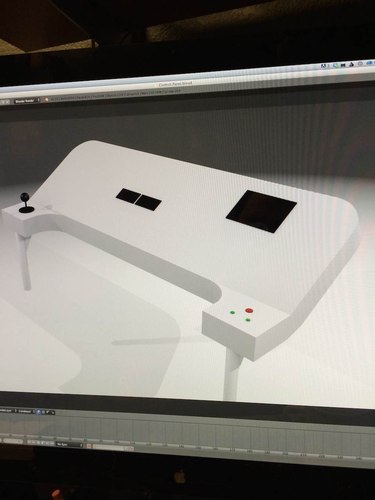
Right now, the control panel enclosure is being fabricated at a metal working place in Phoenix, AZ called Liquid Metal Concepts. They sent over Solid Works images of the enclosure before it was sent off to the laser cutter. Before that, though, I mocked it up in Blender 3D real quickly:

The engineer at Liquid Metal Concepts was fast and created those designs above in no time. I brought them the Ikea chair to discuss attachment hardware and I think we've come up with a pretty cool solution. Can't wait to show everyone.
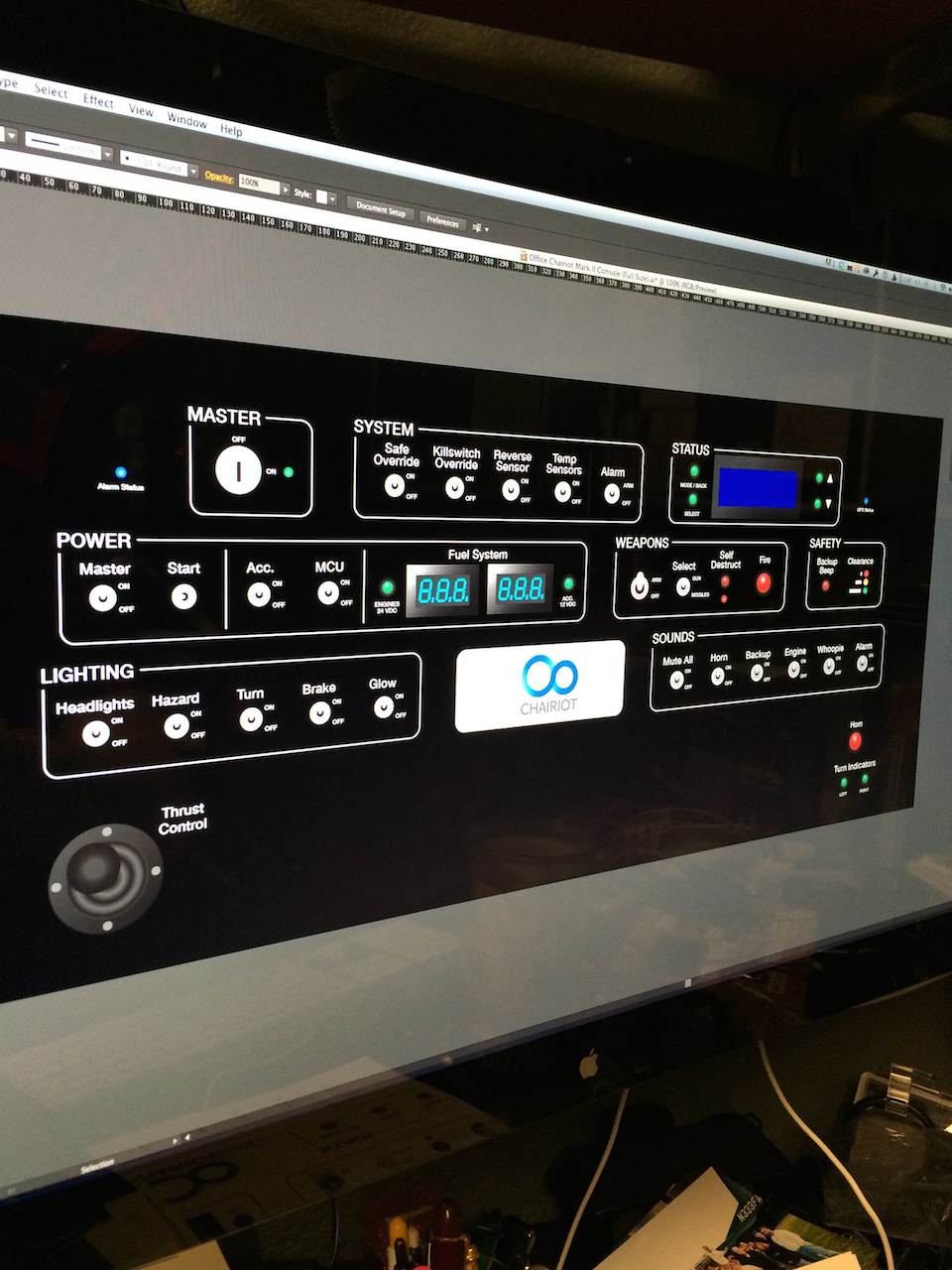
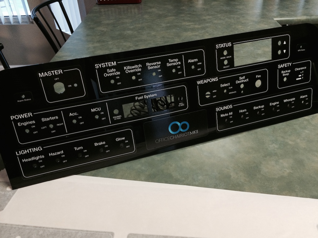
Here is what the decal design for the panel looked like in Adobe Illustrator:
I had two sets of the labeling/graphics overlay for the panel printed at Sign-A-Rama in Tempe, AZ. At the time I ordered, I wasn't sure if I was doing the control panel in black or aluminum. With the aluminum fabrication, of course, I'm going with black ink on transparent decals. I plan on paying the printing people to peel-n-stick the control labels onto the aluminum.
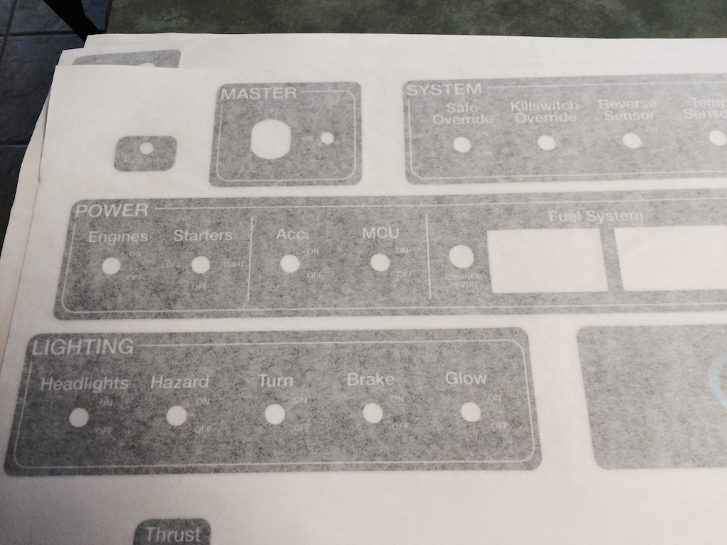
To check the registration (accuracy) or the printing versus the laser cutting of the panel, I used one set of the black decals on the plastic panel that was cut and I have to say, despite my inability to peel-n-stick those bad-boy decals with absolute professional precision, the panel still looks incredible!
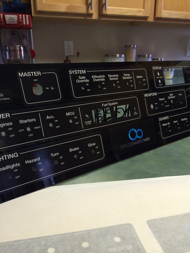
I also had a couple of aluminum panels laser cut before I knew the Liquid Metals guys would laser cut the whole enclosure again. I took the thinner of the two panels I had and inserted the controls for the panel to see how everything fit:

So far, everything looks amazing and it's so crazy to see results coming from my drawings! Fun!!!
Office Chairiot Mk II Power Board and Circuit
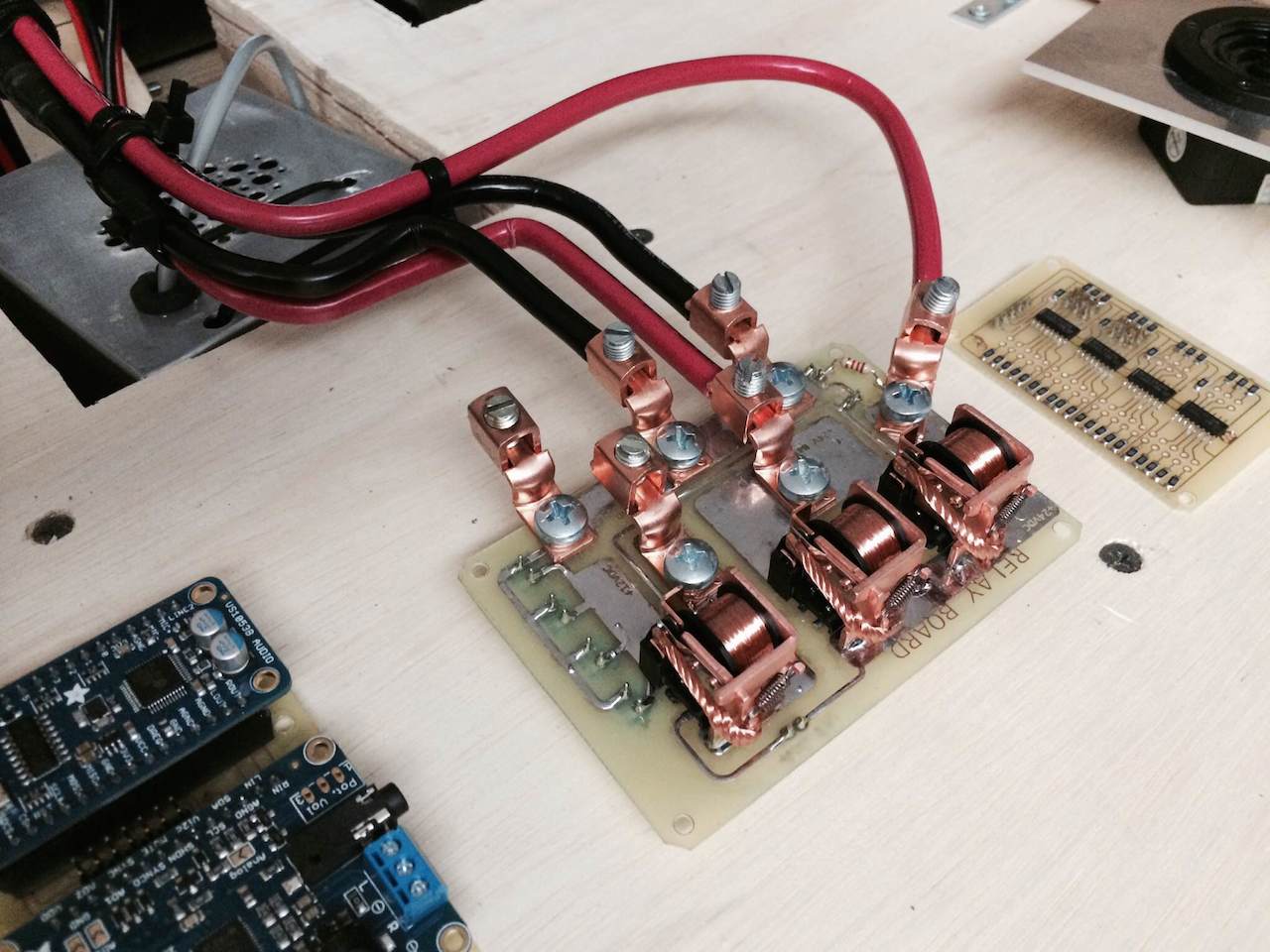
The first edition of the relay PCB that switches the main drive power (24VDC) and the accessories (12VDC) mostly worked OK. I forgot to add a couple of diodes around the relay coils to prevent voltages on the 24V coils when the 12V rail was switched on out-of-sequence. I may require some electrical engineering assistance on this to be sure the power is all OK. The relays are very beefy and to cover the potential current the motors may draw, I put two relays in parallel for the 24V rail.
Here's a picture of the 1st revision board in testing:
This version had no flyback diodes for the relay coils or reverse polarity protection. So, Rev. 2 has all the diodes and more beefy traces and holes for better wire lugs. These are the same ones found on the Sabertooth 2x60 motor controller I'm using from Dimension Engineering, who were kind enough to point me to the manufacturer (LugsDirect.com) of the lugs. Here's a side-by-side comparison of the old lugs I was using (above) versus the new ones from LugsDirect.com:
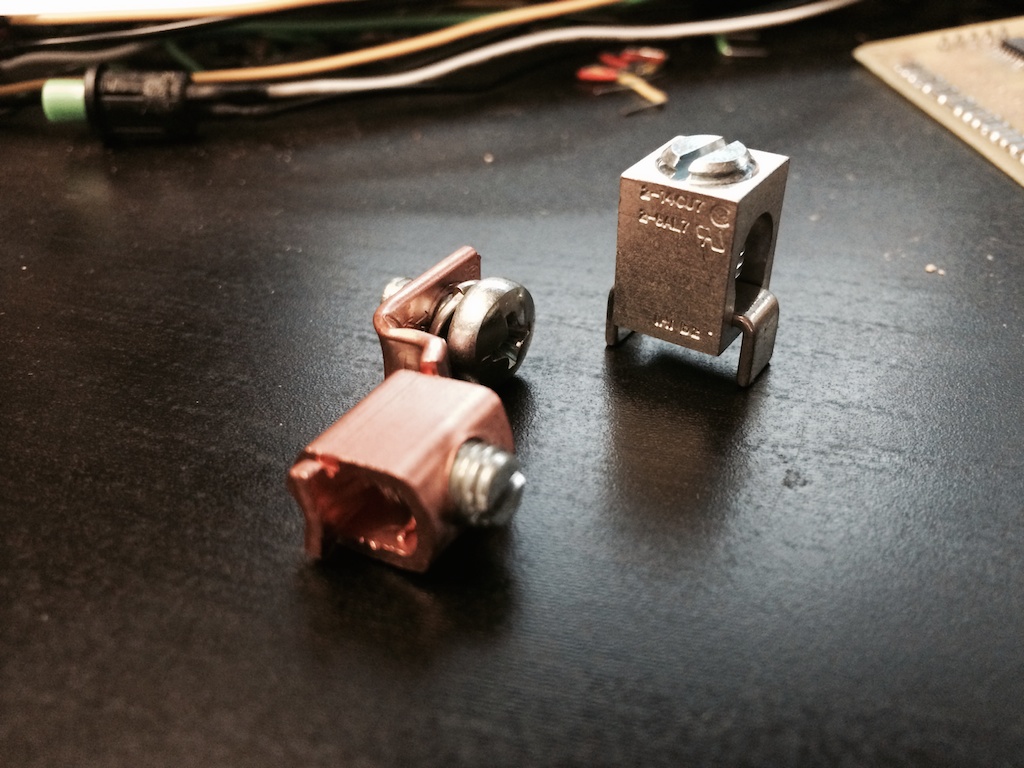
The old ones were screwed onto the board and no matter how tightly I attached them, they could still twist and short lines out. Plus, they were just plain bulky. The news lugs solder down to the board and don't move for anyone in any way. It exactly why Dimension Engineering uses them on their robotics controllers. Here's what the Sabertooth 2x60 looks like with its lugs:
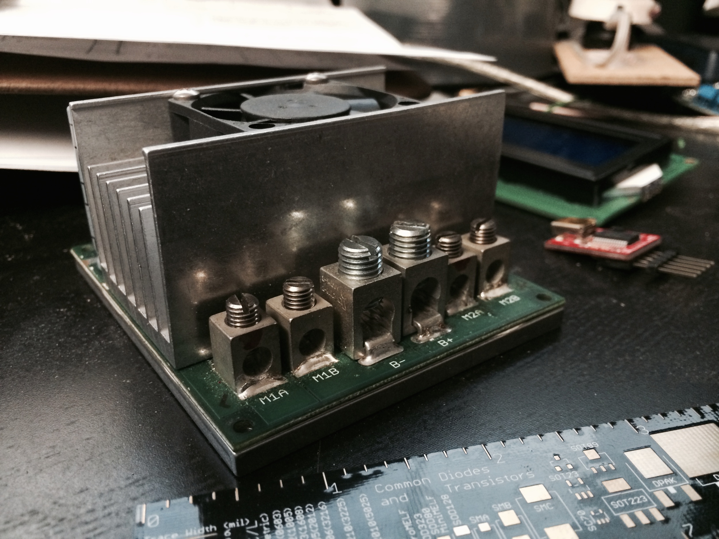
I can tell you that those lugs will not come off that board without the board breaking away. They're awesome. Also, the people at LugsDirecto.com are super-friendly and very, very helpful. I highly recommend you visit their site if you're looking for ways to connect big wire to your project.
The schematic for the new board looks like this:

For the loads after the relays in the 24V and 12V systems, I just put motors and an LED (respectively) as placeholders. If you follow the schematic, you can see that the 12V Accessory power (through D2) cannot be switched on unless the 24V Master power (through D1) is switched on. The Revision 1 board, sadly and stupidly, allowed stuff to be switched on out-of-sequence. Dumb. Fixed.
And the printed circuit looks like this:
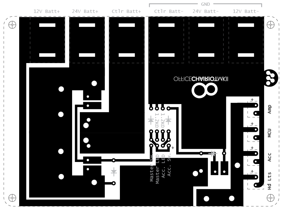
The slots at the top are for the solder-down "straps" in lugs. The lugs are nicely arranged side-by-side. A lesson learned from the rev. 1 board. That 6 AWG wire used between the batteries and the power distribution board and the motor controller are hard to wrangle and they pull on the connectors quite a bit. The lugs will keep those nasty things under control. The lugs will control the wires, not the other way around.
Main Board Design Progress
The main board for this beast is far and away the biggest and most complex circuit board I've ever designed. Er, well, that's not saying much given that I'm an amateur electronics guy with about 5 years of semi-decent experience. Here's a split-image of the printed board with and without the Arduino Mega 2560 on top (in reality, the circuit board would be plugged on top of the Arduino, but this image was a photo of me testing the pin registration between the two):
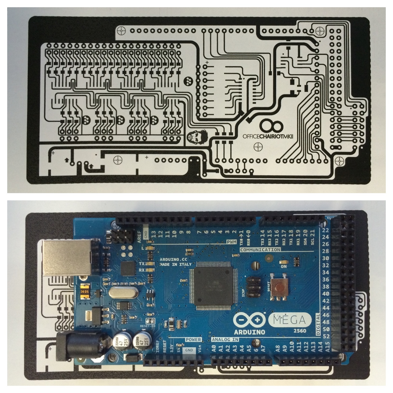
The original plan was to build many little separate boards for the various subsystems (button/switch input, LED output, audio, lighting, etc.). Recently, I started moving some of the less complex boards onto the main board. I argue with myself about this move: 1) Separate boards mean failures in those separate circuits don't kill one monolithic board, 2) All-in-one board means fewer cables and connectors inside the control panel enclosure. I'm risking failure by combining many of the modules into one shield for the Arduino in favor of one really awesome-looking board with lots of neat little parts on it. Sounds dumb written out.
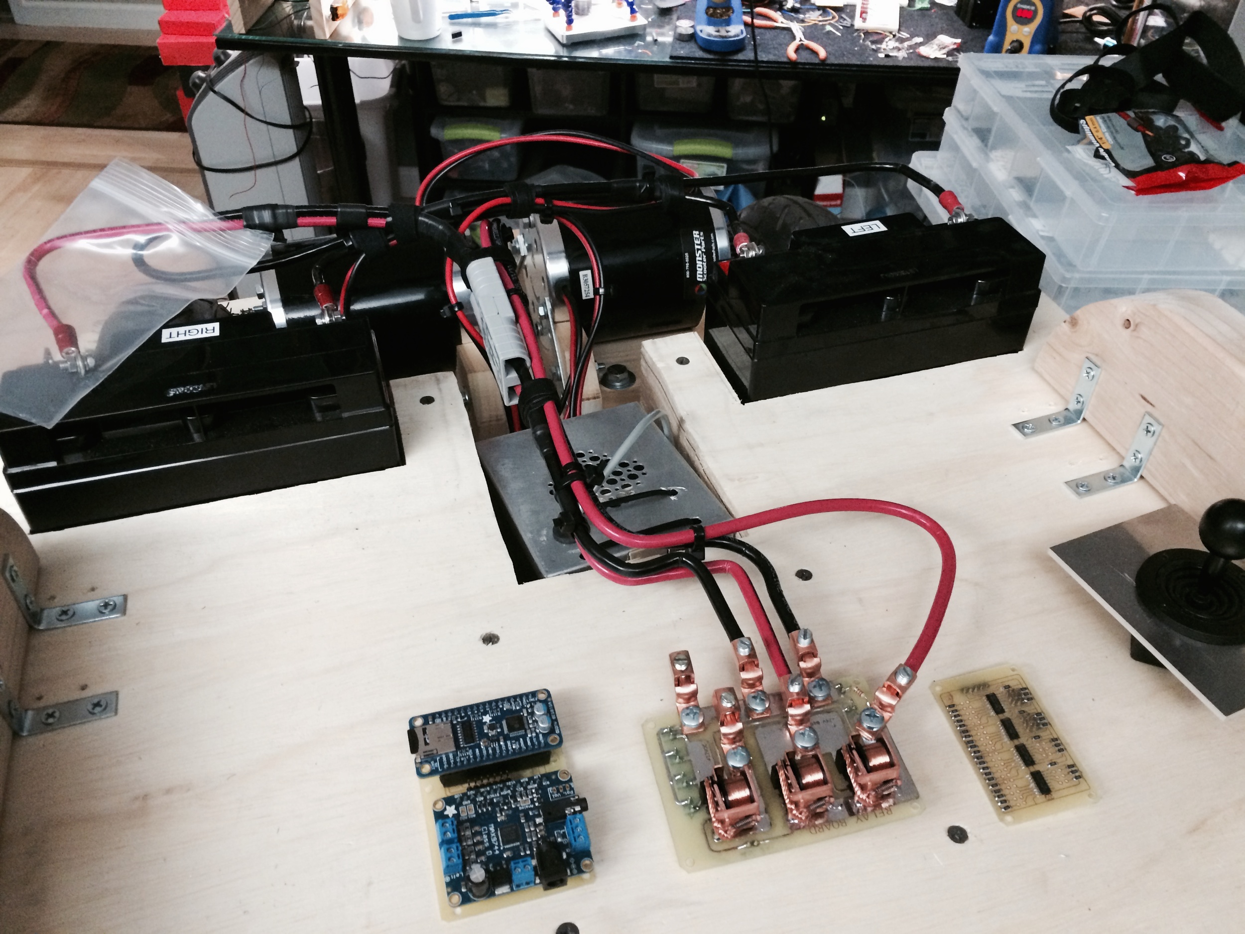
Here's the first revision power distribution board with the old copper lugs, the improperly designed Inputs board and the untested audio module:
I may still go back to the original modular design, but for now, I like the all-in-one board for the simplicity of hooking up all the parts in the control panel and throughout the chairiot.
More to come...