(Editor's Note: When I post stuff about the Office Chairiot, you can generally find nearly the exact same content over at the official Office Chairiot Mark II website. But, PLEASE, don't let that stop you from reading stuff here!)
Above is a picture of all of the circuit boards that make up the brains of the Office Chairiot Mark II control panel. To be sure, it's completely ridiculous. Just wanna make that clear. The only really necessary pieces on the control panel are the main power switch and the joystick. Everything else is there purely to make me feel like I'm piloting a space shuttle or Apollo spacecraft of some sort.
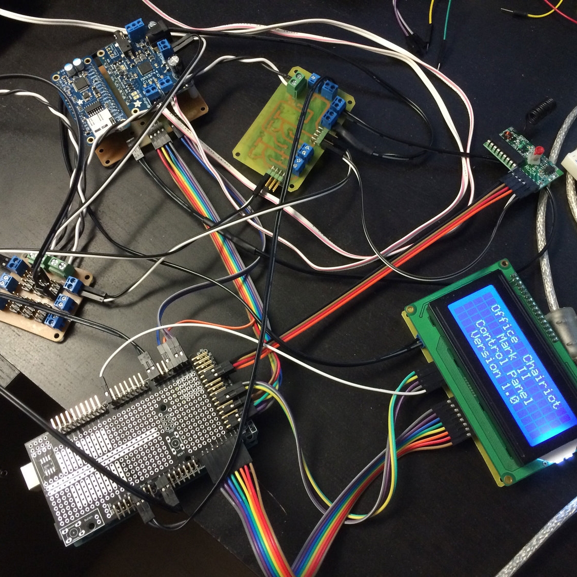
The chassis electronics, on the other hand, have some worthy reasons for existence and they are part of the chassis whether you're using the chair or the wagon or the shelf cart (kinda like a beverage cart, really). Here's the current state of the spaghetti plate that is the chassis electronics:
The 12V AGM battery sitting up in the back is normally sitting down inside that matching hole in the middle. This setup is what things look like when they're on the bench, of course. That battery powers all of the accessories on the Office Chairiot Mark II. The drive system is powered by two more of that type of battery running 24V for the motors and drive controller. The two systems are electrically isolated from one another by opto-isolators.
That silver finned thing in the lower-right of the photo above is a big automotive/marine DC-DC convertor I got on Amazon for pretty cheap. It takes 24V or 12V and steps it down to a nice and efficient 5V for the electronics. It's big because it can also provide upwards of 10A of power to the gadgets. Hence the fins. I think it might be waterproof, too. Not certain. Nothing else on the Office Chairiot is, so...
The Arduino Mega 2560 is the main brain in the chassis. It takes commands over serial (soon to be CAN bus; I just received some Atmel ATmega64M1 microcontrollers with CAN bus transceivers built in) from whatever is currently controlling the whole thing (the control panel, potentially a wireless remote or smartphone, etc.). It controls eight relays to switch 12V power on and off for things like LED lights and turn signals. When it receives motor control commands, it translates those into something useful for the Dimension Engineering Sabertooth 2x60 motor controller.
Everything is working pretty well, at this point. I have to shore up the RGB LED lighting under the chassis. I think I may have toasted a few of those finicky little buggers because I didn't follow best practices in this Neopixel installation. I will be upgrading the circuit to use those practices this weekend. Big honking electrolytic capacitors, resistors, etc.
The control panel is coming together quickly. A number of the original modules I'd designed earlier didn't quite work the way I'd planned, due to various issues like power, grounding issues and whatnot. I've now reworked some of the PCBs and things appear to be working all spiffy-like.
The first major issue I ran across at the SEMA show in Las Vegas (guest of the Local Motors Idea Booth) was power: I had weird ground stuff going on and I even ran into a couple of unintended shorts. So, the first thing I did when I got back was organized my power supplies and routing.
I'm a very firm believer in switching regulators over linear regulators in little DIY projects, at least ones not too affected by EMI. WAY more efficient. Today, it's EASY to use them, too. For this one, I went with regs that could to 1A and that required not much in the way of a supporting cast. I think the datasheet wanted three capacitors for a normal situation. Not that this control panel is by any means "normal," but...
On this board, I used switching regulators from CUI. Part number is V7805-1000-SMT for the 5V surface-mount version and V7803-1000-SMT for the 3.3V version. Here's the datasheet for those: http://www.cui.com/product/resource/v78-1000-smt.pdf
There are plenty of other options available, too. Search around for them. These are not the cheapest, necessarily, but they're reasonable. They're great for me because they only need three capacitors to work in most of my projects. They dissipate heat nicely and they're easy to solder.
The regulator on the left in the picture above is 5V. The other is 3.3V. I don't have any 3.3V stuff, yet, but I figured I'd put one on for expansion later. The GPS module I'm using is a 3.3V part and will actually be a part of the chassis. Mostly because the chassis is what I'd prefer to keep track of: It's upwards of a couple thousand dollars. The IKEA chair is $70.
The bottom of the board has a number of terminals and headers for easy addition of new modules that need 5V or 3.3V, connected whichever way was the way of the day. There are more 5V connections (right side, four terminals, four two-pin headers) available than 3V (left side, two terminals, four two-pin headers). This board runs off the 12V accessory batter in the chassis and the power is very clean, even with the 24V drive system running with those two big motors.
I also had issues right before SEMA with busses in the control panel, mostly because I was rushing to get the thing lit up and drivable in the span of a few weeks. I couldn't find enough easy connections for ground for things like buttons, switches and other modules. I threw together some pretty funny hacks the weekend before the show. I rectified that problem by making an auxiliary and convenient little bus board to help spread the electric love, as it were:
The two green terminals are where the 12V from the battery comes in. The second terminal is there to jump off to the power supply board. The middle set of headers is tied to whatever you connect to the green terminals. One side of the headers is ground, the other is whatever the other wire is (12V, in this case).
The side terminals and headers are their own busses. One side has all of the positive (labeled "+") tied together between the terminals and the heads behind them. Same goes for the opposite side of the board. They're meant for lower power, like 5V and 3V.
ALL of the terminals and headers share the ground on the board so that everything is aware of the same ground level. You can see how they're all connected (or not) in this photo of the bottom of the board:
I forgot to flip the text when I printed the transparency for the image transfer process. Whatevvs. Hold it up to the light and it's totally readable from the other side. :p
This is also one of the first few boards I've built to employ my new "Don't waste etchant" methodology of not wasting etchant. Read: Etch the areas around the traces but not the entire face of the board, if it's OK to do so. I'm not an expert at this, so I'm not sure if I'm violating rules or not, but my boards work and they look cool. They're also quite accurate and have nice fine pitch for being made at home. So there.
All along I was designing a fairly complex snap-on adapter board for the Arduino Mega 2560 to make quick work of connecting all of the modules inside the control panel to the brains of the operation. I then stumbled onto a ready-made board at Adafruit (http://www.adafruit.com/product/192) that did mostly what I was designing, but without the work. :) $15. Can't go wrong.
Next up was the LCD. I just didn't have enough time before SEMA to get my previous version of the LCD board working right, although it turns out it did indeed work OK. However, I wanted to approach how I was connecting that to the Arduino in a new way, so I started fresh.
The LCD was always a bit of an unknown, as far as how the heck I was going to fasten it to the underside of the face of the control panel without adding ugly screw heads. For SEMA, the panel was simply STUCK to the underside of the panel with one of my favorite holding materials, Gorilla Tape. NOW, I've actually put some countersunk holes in the aluminum enclosure under the glossy plastic face to hide them AND I cut a nice spacer from a sheet of plastic for behind the panel face to keep the face of the LCD even. I'll post more on that crazy engineering later. This post is about circuits and stuff.
The adapter board for the LCD is really just that: It's an adapter. It has a female header to bring all of the pins from the Newhaven LCD display (a 4x20 LCD character display: http://www.newhavendisplay.com/nhd0420dznswbbw-p-413.html) to the edge of a board in a way that's easier for me to work with. It also adds a digital potentiometer for the LCD contrast so that the user can change the contrast through the configuration in the control panel firmware. That's the IC in the upper-right of the photo above. There's also a decoupling capacitor on the other side where the power comes in for good measure. The brightness is handled with a PWM channel from the Arduino.
I decided to make the board to have roughly the same footprint as the LCD's PCB so I could bring the screws down through everything for support: Through the panel front, through the plastic spacer around the LCD's black metal frame, through nylon spacers and finally through the adapter board. Nice and snug. "Well connected," if you will.
I run the LCD in 8-bit mode. It's easy enough to do it in 4-bit mode, as well, but I have the pins to do 8. In testing, it's hard to tell the difference between 8-bit vs. 4-bit speeds when you're bit-banging the characters over to the display rather quickly, but versus one of the readily available and easy-to-use serial "backpack" boards, it's definitely quicker. In the micro-level scheme of things, I'm saving some clock cycles sending all 8 bits in one shot.
Next up: Managing all those switches and buttons.
While the Arduino Mega 2560 has a crapload (technical term) of GPIO pins, using them for the 30+ buttons and switches on the Office Chairiot control panel felt wasteful. So, I brought in the shift registers! Yes, there are I/O expander ICs out there, but that's just not as fun or maker-like as making your own expander out of cool, standard logic chips, especially SMD versions of those components. This board has 32 pins that it can shift into the Arduino through just a couple of the Arduino's GPIO pins. It's really handy. It looks tedious to solder (it is), but it's relaxing to sit there and concentrate on soldering and drown out whatever else is going on, like the garbage needing to be taken to the curb or the pool needing cleaning. :) Someday I might move up to solder paste stencils and such.
The board is super-simple to use because the buttons and switches can be connected with simple two-pin female connectors. The pins have pull-up resistors just in case the software guy doesn't enable them on the microcontroller. I never forget, of course.
The audio system has been a royal pain in me bottom (insert minion giggles here). The audio was pretty easy to get up and running on the breadboard, but there were a lot of interconnects between the MP3 player board (http://www.adafruit.com/products/1381) and the 20W Class D amplifier board (http://www.adafruit.com/products/1752), both from the wonderful folks at Adafruit (again). Making sure the PCB to bring them together was designed right was tedious. The one shown here was version 2. Version 1 worked, but version 2 makes better use of space and made routing traces cleaner.
The green stuff on the back of the board is the etch-resist stuff left on from the positive photoresist method I use for making homemade printed circuit boards.
I like the MP3 board from Adafruit because it's pretty easy to use, especially because of the SD card slot. The problem I'm having at the moment is the library, I think. It's locking up my Arduino randomly and I think there is an interrupt issue. We shall see. I'll be talking to Adafruit support about the problem. Otherwise, the sound is great and I like how easy it is to implement, as long as it's cooperating.
The speakers are some nice little 3-inch (maybe-ish) ones I picked up for their response quality. It was a good range, as I recall. Kobitone or something. They weren't the cheapest ones at Mouser, but they have great sound when they're properly enclosed. Plus, they're not that deep, so they'll tuck away into the control panel nicely.
That leads me to the new back piece to the control panel enclosure:
As you can see, I've learned in my time at Local Motors Labs that "speed holes" make a part "go to 11." That features aside, a number of things stand out on this new version:
- Fins on the mounting pillars because the guts for the panel are adding a lot of weight to it making the simple design I have right now a bit flimsy
- Big-ass hole in the back for easier and quicker circuit access (there will be a hinged door there)
- Speaker holes! Yay sound! Also having speaker cover rings made that I'll wrap in something swanky before mounting.
- I think the pillars themselves will be the next diameter up from the first version, whatever that was, can't remember at this moment
The last piece to this update is the remote key fob receiver. It is (again) from Adafruit (http://www.adafruit.com/products/1096). It's SUPER easy to use. Give it 5V, ground and then just have your microcontroller watch the D0, D1, D2 and D3 outputs for HIGH level when a key on the fob is pressed. If you prefer LOW on press, throw an inverter in between. Although, I don't know why you'd waste money on another IC when software can handle just fine. My two cents.
Thank you BOTH meltmedia and Local Motors for all of your help and support! You both rock!