sensor

iPotti #2: After a Number One, We Had to Make a Number Two

iPotti #2: After a Number One, We Had to Make a Number Two

iPotti #2 is the latest incarnation of iPotti, the custom bathroom availability monitoring system I built for my employer, meltmedia. I started designing and building the original iPotti in 2010 and it went into operation in early 2011. At the time, there wasn't anything like it that we were aware of. Lately, some other similar systems have popped up and their inventors have done some pretty cool stuff with them. I've found inspiration to reinvent iPotti. Plus, at meltmedia we'd like to use the device for marketing purposes in the near future.

Since 2011, meltmedia has outgrown its original office where iPotti ("number one") is installed. At that time there were about 20-some-odd meltmedians. Today, there are over 60 of us and we now occupy TWO different office spaces on the same campus. On the plus side, with the growth in the number of meltmedians came a growth in the number of pottis at meltmedia to service those meltmedians. On the not-plus side, there is only ONE iPotti #1 and it only watches TWO of the 9 or 10 pottis across two buildings. This situation needed to be rectumfied. [snicker]

RoboStocking - AVR, Servo, Motor, IR Sensor, and BOOM!!! Merry Christmas!

At the office, we decided we were going to have a stocking decorating contest for Christmas. The rules were pretty lax, so I immediately thought of interactivity and electronics and blinky lights and whatnot. Well, that, and there was no way in you-know-what that I was going to hot glue glitter and spongy letters to a stocking with electricity being involved. Here is a video of the final product to pique your interest:

How did I do it? Easy. Some AVR programming (through my usual Arduino hackery) and some simple electronics and BOOYAH! Motion activated stocking with a Santa sign and some jingle bells.

First step was to make a framework to hold the mechanics and the electronics. I used plexiglass and Lexan to support the pop-up Santa sign and to act as the general body of the mechanical works inside the stocking. The layers of plastic were riveted together.

RoboStocking plastic frame and copper ribs

To push out the stocking into shape to make room for the guts, I took extra heavy gauge copper wire I had in my electrical drawer and used pieces of that for "ribs."

Heavy gauge copper wire as ribs

Copper rib bent 90º and riveted to main plastic frame

The sign was pushed up out of the stocking with a regular hobby servo and some armature work. The plastic worked as a track to keep in straight and sliding smoothly. The armature was made from parts used in RC airplanes I got at a hobby store.

Servo Santa sign linkage

The next thing was to make it motion sensitive. That was initially going to be controller by a PIR sensor, but it turned out to be too whacky. I settled on a nice little sensor by Sharp that I picked up at Sparkfun.com. They simply alter a voltage depending upon what's in front of the sensor and how far away it is. Really simple to experiment with and get a good idea of what numbers to expect from the ADC to trigger the action.

Sharp Long Range IR Proximity Sensor (2Y0A02)

I tried a number of methods for jingling bells. The first was funny, but a bit difficult to implement on the sticking itself. It involved a wheel (or plastic gear, in this case) and a rod with the bells hanging off of it. The idea was that the motor would push and pull the bells rapidly and make them jingle. It worked on the bench, but not in the stocking.

First attempt at mech-jingle bells

The ultimate solution I stuck with was simply a cam on a motor behind the bells. When it ran, it smacked the back of the front face of the stocking where the bells were hanging. It was essentially a big honking 12V phone vibration motor.

 Wood cam that vibrates jingle bells
Wood cam that vibrates jingle bells

Next step: Jingle bells. I tied them to the cheap Chinese-made stocking with thin copper wire as a sort of twisty-tie thing. Worked great. I wasn't very organized about where I put bells, just wanted to get a bunch in the general vicinity of the bell thwacker motor.

Jingle bells randomly stuck to the stocking's face

The brains behind all of this is, as usual, an AVR microcontroller. I use my own version of the Arduino IDE to upload firmware to my AVRs on the breadboard. The code is super simple. It basically just waits in a loop for the ADC to show a value from the IR sensor that meets whatever threshold I figgered out in my experiments with the sensor and ideal distances for triggering the sticking. When it gets a hit, it turns on the MOSFETs for the servo (the sign) and the motor (the bells). It start the motor spinning for hitting the bells and pushes up the sign. After a few alternating blinks of the [not-added-at-this-time] LEDs, it retracts the sign and stops the motor and cuts power to them both. That's pretty much it. Here's the RoboStocking motherboard:

RoboStocking motherboard with socket for ATmega328 microcontroller

I even put holly on the board in the etch. :) Because the wall wart that powers this thing outputs about 20VDC, I put a LM7805 5-volt regulator on the board for the logic stuff and another LM7805 regulator for the motor and servo. There was no reason to run the motor at its full 12 volts. It was only smacking the back of the stocking. There are two regulators because the power draw of the circuitry plus the motor plus the servo was causing the AVR to shutdown. Running on their own circuits gives them each the full power available through the individual regulators.

As always, I drew the circuit board in Adobe Illustrator, flipped it and printed it on my Samsung black and white laser. I've found that running the transfer paper through the laminator four times makes the toner really adhere to the copper without problems. I've notice that after four times, when you drop the board with the transfer paper stuck to it into the water bath, it dissolves off the board pretty quickly. The etch afterward is much higher precision, as well.

Board with printout of circuit to help me place components

The only thing left was to draw a cute sign for the slide-up. It took me a bit of trial and error, but I finally drew a decent cartoon Santa in my normal style and slapped a Christmassy looking font in the sign part of the slide-up thing. This setup makes it look like Santa is just hanging out in the top of the stocking. When he slides up, the actual sign is revealed below him, as if he's pulling it up for you.

Santa sign on RoboStocking

With everything assembled, the guts of RoboStocking look pretty cool:

RoboStocking with SantaSign and RoboGuts

What makes this story funny is that I was not able to finish this silly thing in time for our company Christmas party. I had to put the final touches on it over the weekend and bring it in the Monday following the party. It was met with great reviews, but could not win the contest that had past. :( Oh, well. There's always next Christmas. Sound and lights will be added, I assure you. ;)

iPotti™ Released!

iPotti™ 1.2 bathroom status device So, we have this issue at the office with our single-person bathrooms. We have one "m" bathroom and one "w" bathroom. We have 40+ people in the office. Many people who sit out-of-sight from the bathrooms often walk all the way across our office only to find out that someone else has beaten them to the potti.

To solve this problem, I took a Make Controller from MakingThings.com, wired a couple of Vishay TEMT6000 ambient light sensors (photo transistors) to it, then wrote a Mac desktop app to sit in the status bar to show everyone the status of the pottis. I call it, "iPotti™" and it works awesome!

At the heart of iPotti™ is the Make Controller. It's an Atmel Sam7 ARM microcontroller with the Make Interface Board stuck to it. The Interface Board has Ethernet, USB, power and breakout headers for the pins of the microcontroller. I wrote a slim little piece of firmware for it that simply broadcasts UDP packets with the status of the pottis. It broadcasts a packet about every couple of seconds.

At the receiving end of the iPotti™ system is a little Mac OS X app designed to sit up in the OS X status bar:

iPotti™ in the OS X® Status Menu

iPotti™ Status Menu - Men Busy

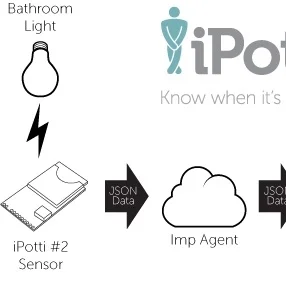
The letters are green when the pottis are available. They turn red when the lights go on inside the bathroom. Lights are the whole trigger in this device. I didn't want to get into sensing AC current in the light wiring or tapping into the switches. This was the cheapest and easiest to get done quickly and without forking out too much coin.

The status menu item has a drop-down menu, as well. It's how you quit the app or check the About dialog:

iPotti™ Menu

The About dialog is pretty simple, but it turns out to be indispensable, since I've now released about three updates to the client software.

iPotti™ About dialog

The sensors see ambient light like the human eye does. I mounted them up above the bathrooms and oriented them to look through little vent holes in the lighting canisters. The light cans keep themselves pretty cool, so there shouldn't be any worries about melting the little sensor thingies. (Read on to see the sensors and their PCBs.) Here is what they look like mounted near the ceiling light cans:

iPotti™ light sensor in position

The sensors are spliced to 4-wire alarm cables that run back to the main iPotti™ server. The two cables join into a single RJ-45 connector (same one used for Ethernet, looks like a big phone jack connector) and then snap into a port in the side of the iPotti™ device box.

Another sweet technical feature of the installation is that our office uses IP phones that get their power from the Ethernet switches. It's call, "POE," which stands for Power Over Ethernet. We bought a little Cisco®/Linksys® POES5 5-Volt splitter that happened to have the proper little coax power connector AND it was the proper polarity, so I didn't have to do anything to hack it together. Here's what it looks like connected up, powering and communicating (outside of the case, of course):

iPotti™ powered over Ethernet

Inside its case, the iPotti™ looks like this:

iPotti™ put together in the case

The Make Controller doesn't fit perfectly in this spare project box I had, but it's good enough for a device that nobody will ever see (hardly ever, anyway). The two white cables protruding from the left side of it are being replaced with the RJ-45 jack for the sensors. Originally, in version 1.0, the cables went right inside the case, wrapped around a screw post for strain relief, and then jacked into the controller.

The latest incarnation (the one that is live and connected now) uses some recovered USB ports from some circuit board I had in my junk pile. I took the ends off of two old USB cables and spliced them onto the ends of the bathroom light sensor cables. I should have done that from the start, but I was lazy and anxious to get this thing up for testing. Now, I can easily disconnect it and update it or maintain it.

The only fab I had to do was on the sensors. They are surface-mount (SMD) and they require a resistor, so I made little PCBs for them using my usual toner-transfer process:

Spare or reject sensor PCBs

Fully assembled, they each look like this:

iPotti™ ambient light sensor

The real trick will be getting people to remember to turn of the lights behind them. We've had signs up for the for the longest time to remind people. Occasionally, someone does forget. Overall, the solution works well.

Lessons learned from this project: A little Make Controller doesn't fair well as a web server when 40+ workstations are hitting it every two seconds. The 1.0 version of the system had the iPotti™ main device set up as a web server and the iPotti™ app hit the server every couple of seconds. This was painful and dumb. I chose that over UDP out of laziness and fear of the unknown (I had never set up UDP broadcasts on the Make Controller's lightweight IP stack AND I hadn't done it yet in my Cocoa [Mac OS X] development adventures). Turns out that UDP was stupidly simple to implement on the Make Controller AND for OS X. I should have done it from the get-go.

Here are some other photos of the installation and a famous red box...

Do not lick soldering irons

SparkFun box!!!

Designer and his new creation