servo

How To Compete in Your Company's FitBit Walk Competition While Injured

How To Compete in Your Company's FitBit Walk Competition While Injured

I built a machine to walk my FitBit for me. I call it the FitBit Cheat-O-Matic! Why? Our office is having a FitBit competition this month (November 2013). In preparing for the competition I overworked my Achilles tendon and could not participate. So, I adopted the mantra:

If you can't join 'em, beat 'em.

The FitBit Cheat-O-Matic is a machine that shakes my FitBit for me 24 hours a day, 7 days a week and does it faster than my normal walking pace. I suppose it's actually faster than most people can run, for that matter. Sure it's cheating! Not only is it cheating, but it's cheating at a level that's so blatant it can't be mistaken for anything else! It's fully disqualified from the competition, of course. But the point is no longer to win the competition, but to be totally ridiculous and to rack up outrageous FitBit stats and make people laugh or maybe shake their heads.

RoboStocking - AVR, Servo, Motor, IR Sensor, and BOOM!!! Merry Christmas!

At the office, we decided we were going to have a stocking decorating contest for Christmas. The rules were pretty lax, so I immediately thought of interactivity and electronics and blinky lights and whatnot. Well, that, and there was no way in you-know-what that I was going to hot glue glitter and spongy letters to a stocking with electricity being involved. Here is a video of the final product to pique your interest:

How did I do it? Easy. Some AVR programming (through my usual Arduino hackery) and some simple electronics and BOOYAH! Motion activated stocking with a Santa sign and some jingle bells.

First step was to make a framework to hold the mechanics and the electronics. I used plexiglass and Lexan to support the pop-up Santa sign and to act as the general body of the mechanical works inside the stocking. The layers of plastic were riveted together.

RoboStocking plastic frame and copper ribs

To push out the stocking into shape to make room for the guts, I took extra heavy gauge copper wire I had in my electrical drawer and used pieces of that for "ribs."

Heavy gauge copper wire as ribs

Copper rib bent 90º and riveted to main plastic frame

The sign was pushed up out of the stocking with a regular hobby servo and some armature work. The plastic worked as a track to keep in straight and sliding smoothly. The armature was made from parts used in RC airplanes I got at a hobby store.

Servo Santa sign linkage

The next thing was to make it motion sensitive. That was initially going to be controller by a PIR sensor, but it turned out to be too whacky. I settled on a nice little sensor by Sharp that I picked up at Sparkfun.com. They simply alter a voltage depending upon what's in front of the sensor and how far away it is. Really simple to experiment with and get a good idea of what numbers to expect from the ADC to trigger the action.

Sharp Long Range IR Proximity Sensor (2Y0A02)

I tried a number of methods for jingling bells. The first was funny, but a bit difficult to implement on the sticking itself. It involved a wheel (or plastic gear, in this case) and a rod with the bells hanging off of it. The idea was that the motor would push and pull the bells rapidly and make them jingle. It worked on the bench, but not in the stocking.

First attempt at mech-jingle bells

The ultimate solution I stuck with was simply a cam on a motor behind the bells. When it ran, it smacked the back of the front face of the stocking where the bells were hanging. It was essentially a big honking 12V phone vibration motor.

 Wood cam that vibrates jingle bells
Wood cam that vibrates jingle bells

Next step: Jingle bells. I tied them to the cheap Chinese-made stocking with thin copper wire as a sort of twisty-tie thing. Worked great. I wasn't very organized about where I put bells, just wanted to get a bunch in the general vicinity of the bell thwacker motor.

Jingle bells randomly stuck to the stocking's face

The brains behind all of this is, as usual, an AVR microcontroller. I use my own version of the Arduino IDE to upload firmware to my AVRs on the breadboard. The code is super simple. It basically just waits in a loop for the ADC to show a value from the IR sensor that meets whatever threshold I figgered out in my experiments with the sensor and ideal distances for triggering the sticking. When it gets a hit, it turns on the MOSFETs for the servo (the sign) and the motor (the bells). It start the motor spinning for hitting the bells and pushes up the sign. After a few alternating blinks of the [not-added-at-this-time] LEDs, it retracts the sign and stops the motor and cuts power to them both. That's pretty much it. Here's the RoboStocking motherboard:

RoboStocking motherboard with socket for ATmega328 microcontroller

I even put holly on the board in the etch. :) Because the wall wart that powers this thing outputs about 20VDC, I put a LM7805 5-volt regulator on the board for the logic stuff and another LM7805 regulator for the motor and servo. There was no reason to run the motor at its full 12 volts. It was only smacking the back of the stocking. There are two regulators because the power draw of the circuitry plus the motor plus the servo was causing the AVR to shutdown. Running on their own circuits gives them each the full power available through the individual regulators.

As always, I drew the circuit board in Adobe Illustrator, flipped it and printed it on my Samsung black and white laser. I've found that running the transfer paper through the laminator four times makes the toner really adhere to the copper without problems. I've notice that after four times, when you drop the board with the transfer paper stuck to it into the water bath, it dissolves off the board pretty quickly. The etch afterward is much higher precision, as well.

Board with printout of circuit to help me place components

The only thing left was to draw a cute sign for the slide-up. It took me a bit of trial and error, but I finally drew a decent cartoon Santa in my normal style and slapped a Christmassy looking font in the sign part of the slide-up thing. This setup makes it look like Santa is just hanging out in the top of the stocking. When he slides up, the actual sign is revealed below him, as if he's pulling it up for you.

Santa sign on RoboStocking

With everything assembled, the guts of RoboStocking look pretty cool:

RoboStocking with SantaSign and RoboGuts

What makes this story funny is that I was not able to finish this silly thing in time for our company Christmas party. I had to put the final touches on it over the weekend and bring it in the Monday following the party. It was met with great reviews, but could not win the contest that had past. :( Oh, well. There's always next Christmas. Sound and lights will be added, I assure you. ;)

My Very Own Useless Machine Ever!!! (Finally!)

I finally finished my own UME Mark II for my own desk for me! Woohoo! My flavor of useless machines ever has a "presidential" look, as some have put it. Latest UME Mk II

This latest model is the first version of the UME Mk II that incorporates a small PCB (printed circuit board) underneath the lid that is attached directly to the pins of the On/Off switch and the two LEDs. It has all the discrete components required to drive the modified servo. It saves time in soldering and it tidies up the wiring under the hood of this magnificent machine.

UME Mk II PCB v1

The wiring that is there comes from the servo, the "parking" switch, and the battery. The next machine I make will have slightly better placement of the board relative to the arm. The clearance was a little tight for my taste, but it still turned out great. This first version of the integrated PCB required some hand-tweaking. I had to cut a couple traces, solder a couple of jumper wires, and notch a little corner out of the board to allow clearance for the parking switch.

The parking switch is the little microswitch inside the box that the arm trips when it retracts back into the box. Its purpose is to cut power on the back swing of the arm. When you flip the On/Off switch to On on the top of the machine, you give power to the circuit and the arm releases the parking switch. When the arm moves the On/Off switch to Off, it actually reverses its own direction. It then heads back into the box until it presses the parking switch, which cuts off power again.

UME Mk II PCB Diagram

The "3.2" version number is truthful: I revised that silly drawing about 3.2 times. The one above is the latest that incorporates the cuts in the traces I had to make on my machine's PCB. It also takes into account the trimming I did in one corner of the board. In the diagram, I just trimmed the entire edge so that it was still rectangular and easier to cut out.

Everywhere you see black is where there would be copper left on the PCB when etching is completed. The green lines and labels are there for reference but are not printed on the final PCB. The white lettering in the black gets etched out of the copper on the PCB. The little circles at the ends of the traces and a few other places in the black areas are drilled with little bits under my drill press. The final PCB turns out nicely, for a home-brew board, I think.

Turn a Servo Into an Inexpensive Geared Motor

In my UME Mark II's (UME = "Useless Machine Ever"), originally I would program an Atmel AVR microcontroller to turn an RC servo forward and backward using timed pulses like you're supposed to. But, when you want to build many machines, microcontrollers are not the way to go. Simple polarity-changing circuits are the way to go. But, you still want the RPMs of a servo without the hassle of the pulsing control. So, you hack the servo and make it a geared motor. Easy! Here's how... Futaba S3004 servo intact

Grab yourself one o' them thar RC servos for a good price at your local hobby shop or on-line. They look so innocent. If you listen, they make a whimpering sound because they know that phillips head screwdriver in your hand is there for kicks.

Take off the armature thing.

I hope that my lack of knowledge in all that I do is entertaining and not a hinderance in the usefulness of these posts. :) So, that said, look at the above picture. I took off the star-shaped armature thingie.

Remove l-o-n-g screws holding the whole thing together.

Unscrew the screws in the bottom of the case of the servo-soon-to-be-geared-motor.

Take off the back. See neato circuitry.

Remove the cover on the bottom of the servo. You'll see nifty circuitry and the spots where the three wires are soldered to the board.

See the wonderful gears and pins and such

Carefully remove the top of the servo that contains the gears and pins and lubricating goo. I bold the word, "carefully" because you need to put this all back in the way it came out. If you can't get it all back together, you will have a nice pile of gears, pins, circuitry, a plastic case, some wire, and a neato DC motor. Take pictures if these don't cut mustard. They can help back track the destruction and make it reversible.

Shimmy the neato circuitry and motor guts out of the plastic case.

Shimmy the neato circuitry and motor guts out of the plastic case. The potentiometer (black thing standing on thick leads opposite the motor) is used by the circuitry to indicate where the shaft is positioned at any given moment. Once the hack is complete, it will be unused. I'll give you some options for it later on.

Desolder the three wires from the board.

I used my ACMG robot (aligator clip magnifying glass) to hold the guts while I worked. Desolder the three wires from the board. Remember not to heat the stuff you work on with the soldering iron for too long. That heat can travel to components that don't like warm weather and can cause severe rash or sunburn or death.

Solder the red and black wires to the motor leads.

Solder the red and black wires to the motor leads. Once you do this, the servo is simply an inexpensive geared motor. The robot makes this very easy to do. You can use a wife, girlfriend, son, daughter, or even an uncle to hold the work, but they're nowhere near as steady as a the alligator clips.

Route them between the pokey little component leads.

Wires soldered. Route them between the pokey little component leads sticking out of the bottom of the neato circuit board because there isn't much room between the PCB and the case cover and the wires have to travel across the board to the hole in the case. I like the path I chose. It looks like a... Well, it doesn't look like anything, but you can pretend.

Looking at the underside of the top of the servo

View of the servo... Er, almost-a-geared-motor (now) looking at the underside of the top of the servo (with the gears) and the top of the main body (at right). The bearings on the black gear are tiny and cool. That black gear has a little nub on it that acts as a stop at one of two positions 180 degrees from each other in the rotation of that shaft. We need that snipped off and trimmed.

See the nub? It's what I'm holding onto with the wire cutters.

See the nub? It's what I'm holding onto with the wire cutters. You need to trim that down flush with the shaft and with the face of the gear (the part of the gear parallel to the back side of the wire cutters in this photo). That will prevent the gear from stopping against the stops that are built into the case of the servo.

Make sure there are not bits left behind or you will hear clicking as those remnants click past the stops in the gear box.

Look on the right side of the gear, just below the bearings on the rear of the face of the gear. Make sure there are not bits left behind or you will hear clicking as those remnants click past the stops in the gear box. I suppose you could clip the stops, as well. But, you can see in this photo that I have a little bit of trimming to do, yet.

Use your new geared motor at will.

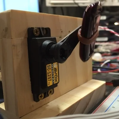
Use your new geared motor as you wish. I learned to circumvent the circuitry on these from various posts on the IntarWebs. It's not hard at all. If you screw up, the servos I found locally at the hobby shop were only about $12, so it isn't the end of the world if you fubar one. In the photo above, you can see the unfinished tops and "robotic arms" from one of the Useless Machines (see post on my site about this device).