Projects

Standing Desk Improvisation Inspiration with Little Perspiration

Standing Desk Improvisation Inspiration with Little Perspiration

Today at the office, I walked by a coworker's desk and something was different: She'd put an Ikea table and shelf together and set them on top of her desk. Nutty, at first glance. Purposeful, after 0.25 seconds of thought. Here's the story of what I saw: Inexpensive IKEA furniture repurposed for other ingenius uses.

Lipstick Camera Turned Video Microscope

Backstory: In a previous life, I was a freefall photographer. I took photos and shot video while skydiving. Before GoPro and others started popping up on the scene, I had devised a little rig for shooting freefall video without the need for the bulky miniDV camera on my helmet. The setup used a "bullet" or "lipstick" camera which provided a video input signal for a miniDV camera (used as a tape deck at this point) located OFF my helmet and in a pouch under my jumpsuit. I don't remember where I got the camera. They can be found on the InterWebs for $100-ish, maybe less. Anyhoo, if you've ever stuck your hand out of the window of a car moving at highway speed, I'm pretty sure you'll be able to figure out how non-aerodynamic a miniDV camera is. Needless to say, a lipstick camera cuts through the wind WAY easier than a full-on Sony TRV-20 miniDV camera. A lipstick camera also weighs considerably less than a miniDV camera. Lipstick Camera

OK, now that I've barfed out a giant intro paragraph, let's get to the nutty-tasting inside of this story: I have this lipstick camera sitting around in a box. I know that when I twist the lens away from the sensor, the camera acts more and more like a video microscope. I have many tiny things I'd like to look at with minimal camera shake.

Focusing the Lens by Rotating It

Neato. In fact, this thing is an excellent tool for reading the tiny, tiny lettering on tiny, tiny surface mount devices ("SMDs") on tiny, tiny circuit boards that I am studying. The problem is holding it steady enough and having a free hand (two is even better) to move around the object under study and take notes. (There are more samples at the end of this article.)

Video Microscope In Action

My eyes are pretty good considering the amount of time they spend staring at computer screens and my age, but occasionally I run across some parts or circuits where there is no way I can easily read the tiny print without magnification. The image above is coming from the lipstick camera and is being shown on a 3.5-inch NTSC/PAL TFT monitor I picked up at Adafruit Industries.

Holding the camera sounds like a job for a gooseneck from a cheap lamp. Thanks, Ace Hardware! Got one. $12. Unscrew some parts, gut some stuff and boom! Microscope camera stand:

Gutted Gooseneck Lamp

I repurposed some of the DIY mounting hardware I used to keep the little camera on my skydiving helmet. Two plastic brackets and some screws from Home Depot (as I recall) and a piece of yoga mat to grip it better, as it was flying with me through 120+ MPH winds.

Helmet Mounting Hardware

I adapted it to the gooseneck lamp by flattening the bracket on the end of the gooseneck and simply screwing the brackets into it.

Camera Mounted on Gooseneck

That was attempt number one, anyway. I routed the cable for the camera, which includes its video signal and power wires, down the gooseneck. The power and video out connectors are routed out of the lamps power cord hole. I dug through my prodigious collection of random screws, nuts and washers and found some #6 pieces that worked like a charm:

Assembled Microscope Head

Here are some things I looked at with my nifty video microscope:

Device to Control Sony Cameras

PIC in Sony Control Device

The device pictured above was used on my skydiving helmet to turn the Sony camera on and off. I can't remember its name anymore. It was very cool. It had a multi-color LED that was fixed to my eyepiece for targeting the camera in freefall. I could get status from the camera, like when it was running low on fuel and tape. The single button make it super easy to work. Prior to devices like that, you had to have someone tell you that the red record light was on before climbing out of the plane.

My Eyeball

That image makes my iris look blue or grey, but it is in fact greenish-brown. Taking a picture of an LCD with my iPhone doesn't really keep a color profile intact, of course.

Resistor and Tiny SMD LED

That resistor is a 1/4-WATT, regular old resistor you've put in a thousand projects. The little dood next to it is the tiniest SMD LED I've ever seen. I had purchased and bunch of those little guys for a clock project and had no idea just how freaking tiny they were until I got them in-hand. No. Way. On. Earth. ...Am I gonna figure out way to solder those puppies to something and make them work. Funny thing about that particular one pictured above: I had lost it for months. While I was putting this microscope together, it just showed up next to another not-quite-as-tiny SMD LED I was examining. I think it was stuck to the edge of the ESD foam on my table and just dropped off by coincidence. It's blue, if you're wondering. Intensely blue with 3 volts.

Scoping a Twenty Dollar Bill

Twenty Dollar Bill Magnified

Currency is always fun to scope.

So, the next step in this project will be to make the LCD look nice and maybe conveniently mount it to the base of the scope. I dunno, yet. I have two of these little LCDs and each of them has two inputs. I might use the other one for a forward-looking camera on my RAM 1500 truck. Who knows?

Making Mad Props for meltmedia's Interactive Superhero Marketing Launch: The Rest of the Props

This is the 3rd in a series of articles about the props I built for my company's internal marketing launch, which was themed around superheroes. I had to wait to write these three articles because we hadn't launched yet when I had finished the props. This article focusses on the last partner prop and the simplest of the three, plus the capes, boots, masks and toolbelts used as props near the front doors of our office spaces (making it look like the meltmedia Interactive Superheroes had come in and hung up their stuff on coatracks after a long day of saving organizations from mediocre designs). Here is one of the coatracks with the Interactive Superhero uniform:

meltmedia Interactive Superhero Uniform on Coatrack

Before we get to the cape and the boots and whatnot, let's talk really quickly about Dave's BEER Goggles Interactive Superhero tool of choice:

BEER Goggles

I've always wondered what tangible BEER Goggles would look like. We all know when you hear the term, it usually means a state of drunkenness, not a physical piece of eyewear. I had an old pair of goggles lying around from my skydiving days and a pair of drinking straw glasses I'd gotten as a gift. Add a little copper wire to hold the straw to the goggles and BAM! BEER Goggles you can really wear! Here is what our creative partner Dave looks like in his incredibly fashionable and highly functional BEER Goggles:

BEER Goggles on Dave

The next big project in my quest to be meltmedia's "Mr. Fox," master superhero tool and weapon maker, was the set of five superhero capes, three of which were to be worn by our company's partners. As it turns out, I do indeed know how to sew, so I set out to find patterns for capes. Unfortunately, I had a hard time find good adult sized patterns, so I used my wife as a model to get a roughly OK cape pattern measured out. I ran to JoAnn Fabric and bought a bunch of satin-esque fabric and some heavier grey cotton fabric to use as backing. I laid out the two long pieces of fabric and started cutting the five rough rectangles out for each cape:

DIY Superhero Cape Backing Cotton Fabric

I figured out the pattern and cut the first piece from the cotton backing, thinking if I screwed up on that, I still had the intact satin to make capes from:

DIY Superhero Cape Basic Pattern for Adults

Next, I started copying the pattern to the other fabric and pieces until I had five of each kind of fabric:

DIY Superhero Cape Pattern Transfer to Satin

With the extra fabric on the edges for the seams, the pattern looks like this:

DIY Superhero Cape Complete Pattern

To make my hands even steadier than they usually are, I sipped bourbon while using the sewing machine (technically, it was Maker's White, which is Maker's Mark before it goes into the barrel for aging) (irrelevant to this story, but interesting, no?):

Cape Sewing Machine with Bourbon

Notice in the background that I did actually use pins to hold the two pieces of fabric in place together while I stitched them together.

A trick that took me TWO capes to figure out was the ironing of the seams. I had to flatten the seams and then fold them and iron again to get a nice edge where the cape and its backing met, kinda like on suit vests, I guess. The trick was to wait to stitch up the bottom edge of the cape so that the cape could be pulled over the end of the ironing board, like pant legs:

DIY Superhero Cape Open Ended on Ironing Board

What this allowed me to do more easily was to push out the seams all of the way to where the stitching was visible so that I could completely flatten the seams, then fold them and iron them nice and clean so they come together at the edges perfectly (or as perfectly as a novice like me can get them):

DIY Superhero Cape Edges Cleanly Ironed

The neck part just needed a little Velcro® and BOOM! Custom-designed, sturdy, lined, shiny superhero capes! Check it:

DIY Superhero Cape Finished, Pre-Silkscreen

Then, here is an action shot of a cape with the meltmedia logo silkscreened onto it:

meltmedia DIY Interactive Superhero Cape Action Shot

Now, the boots took a little trial and error. The first pair I found I thought would work really well but turned out to be a horrible idea. They were diving boots made from neoprene. What's the take-away from this? Neoprene soaks up paint like nobody's business. But, here was how I masked one off for painting:

Neoprene Diving Boot to be Painted: Bad Idea

Plan B: Get on Amazon and order actual superhero costume boots, like these (I guess the pointy tops make them not-average-citizen boots):

Superhero Boots Pre-Paint

I put a coat of primer on 'em and then spray-painted them our superhero blue:

Superhero Boots Painted

The final touch was to get the meltmedia logo on them. To save myself the hassle of cutting all weekend, I just printed the logo in reverse in a circle, but the cutout logo was printed in a color as close to the paint as I could get it on my HP Color LaserJet. That way, I only had to cut out circles. Easy-peasy:

Boots Painted and with Logo

Next item up for making? Superhero utility belts! For these, I took a couple of leather belts from Target, riveted a couple of Home Depot gift card containers and a Tic Tac container and painted it all, masking off the brass buckle, of course:

DIY Superhero Utility Belt with Containers Riveted On

Next step was the paint:

DIY Superhero Utility Belt with Paint

Finally, add one of them swanky meltmedia logos with the blue knockouts and SHAZAM! meltmedia Interactive Superhero official utility belts matched to official meltmedia Interactive Superhero costumes:

DIY Superhero Utility Belt Matched with Costume

The last piece to complete the costumer is the mask. I didn't spend much time on these. They weren't meant to be worn. I put a sheet of overhead transparency film over my wife's face and drew a superhero-looking mask in Sharpie. I then transfered that into Adobe Illustrator by way of the flatbed scanner and cleaned up the lines. I printed patterns of the mask on regular paper with dashed lines. I then took a razor blade and cut out the masks from blue foam board stuff (er, whatever it's called):

DIY Superhero Mask Pattern

Cut outs and headband pieces, too:

DIY Superhero Masks Cut Out

You can't even tell who's behind the superhero mask, they're THAT good!

DIY Superhero Masks In Action

So, that's the story of how I spent three weekends playing meltmedia's own Mr. Fox, making mad props, playing with electronics, tinkering with foam and making homemade DIY movie magic, even though there isn't a movie featuring the props. ... Or is there? ;)

Making Mad Props for meltmedia's Interactive Superhero Marketing Launch: The HAT

This is the second in a series of three posts that talk about the props I built for my company's internal marketing plan launch for the employees (see previous post for back story). This particular post is about the HAT (Helmet for Accentuating Telepathy) and is our managing partner Justin's Interactive Superhero tool of choice. It allows his Techno Telepathy to reach farther than it would otherwise with the flick of a switch. The blinking LED on the end of the highly tuned antenna tells him his Techno Telepathy is sensing with ludicrous sensitivity. Er, something along those lines. The HAT started life as a simple chrome (plastic that looked like chrome) skateboarding helmet, which means you, too can build a HAT for accentuating your telepathy (if you imagine REALLY hard):

HAT Brand New in Box

The main purpose of the HAT is to make Justin, one of meltmedia's partners, look like a dingbat (the plunger helps a little, as well):

HAT on Justin

The next thing to do was to make a blinky LED circuit. The cheap and easy way is to use a 555 timer IC, a couple of resistors and a couple of of capacitors:

HAT Circuit with 555 Timer

I dead-bugged it to save time and to make it nice and compact, as I wanted to hot-glue it into the foam inside the helmet, like so:

HAT Circuit in Foam

I added a toggle switch to the outside of the helmet to allow Justin to turn off the telepathy accentuation feature and return the helmet to its normal state of being a plain old goofy helmet:

HAT Toggle Switch

The antenna was a thick piece of electrical wire I had left over from my pool computer upgrade last summer. I wrapped a section of it around a pen, soldered one of the LED leads to it, then wrapped another thinner gauge wire up the thicker wire to provide ground to the LED (it's possible I had the polarity the other way, but you get the idea). I put a little heat-shrink tubing on it to better fixate the LED onto the end of the antenna:

HAT Antenna with Heat Shrink and LED

The antenna and most every other thing attached to the helmet was held in place with crap-tonnes (the European measure of a crap-load) of hot glue (sorry for the blurry photo, BTW):

HAT Hot Glue Party

And, finally, a video to show it in action:

Making Mad Props for meltmedia's Interactive Superhero Marketing Launch: Techno HAMMER

I believe I've mentioned it before: I work at an amazing web and software development shop called, "meltmedia." We have a gaggle of highly talented software engineers, web developers and designers. Sometime back in 2011, meltmedia was in search of  a new tag line to kick off a for-real live marketing campaign. Marketing was something melt hadn't worried about before then. While in San Francisco at the 2011 Apple World Wide Developer Conference, in a bourbon-fueled barrage of submissions to the company's on-line suggestion box for new company tag lines, I came up with, "We are Interactive Superheroes." It stuck and I won a $90 bottle of bourbon. Woohoo! To be clear, I am fueled by many things: Caffeine, sugar, soda, etc., not just bourbon. I like chocolate milk. I happen to be a major bourbon geek and had been sampling fine bourbons at a speakeasy in San Francisco called, "Bourbon & Branch" before I went back to the hotel and started submitting dozens of mostly silly ideas for meltmedia's new tag line.

For the short attention span version of this, here is a photo of the three partners of meltmedia in their full costumes with their props:

meltmedia Partners in Full Costume and Props

We'll start with the biggest prop: Mike's Techno HAMMER (Highly Active Mike Moulton Energy Repeater). I needed this thing to be big. I didn't have much time for any of these props, especially the HAMMER. To sturdy up the thing and to keep it as lightweight as possible, I started with green foam from Michael's:

HAMMER Foam Interior

The handle is a piece of PVC pipe from my pool equipment upgrade last year. I knew I'd eventually find a use for the pipe!

At first, I wasn't going to get all electronicky on this thing, but it just didn't seem right to have a TECHNO HAMMER without random blinking LEDs on recycled circuit boards, so, this thing needed a circuit to make random LEDs blink. It also needed a way for Mike to turn on and off the LEDs at will. I did this by embedding a standard pushbutton in the handle:

HAMMER Pushbutton in Handle

I cut a hole for the button, then cut a BIG hole behind it to allow me access for glueing. To be sure the button would be at least somewhat difficult to push through the handle, I jammed a piece of leftover green foam into the handle and behind the button before I closed up the back of the handle:

HAMMER Foam in Handle

To crappily simulate leather wrapping on the handle, you can see in the image above that I took strips of Gorilla® tape and folded one edge, then wrapped up the handle at an angle. It kinda did the trick. Ya do what ya can in the time ya have, ya know?

The button was in between the batteries and the LED blinking circuit. A simple momentary power-on functionality. The circuit was an Atmel® ATmega328 AVR® microcontroller (same one used in certain models of the Arduino). It was programmed to strobe the LEDs (rifle through each of them and turn them on or off many times per second, like a TV scanline). To keep the current draw to a minimum (to prevent the AVR from cooking), I had all of the LEDs cathodes return to ground through a dinky little constant current devices (CCD) from ON Semiconductor (part number NSI45020T1G). There are 12 LEDs. 12 pins on the AVR are randomly set to be on during their time slice or off. The little CCD kept the current to 20 mA for each LED. This allowed me to use red, green, yellow, and orange LEDs, regardless of their required forward voltage, since the current was always 20 mA, which they all liked. The other reason for doing it this way instead of a resistor was power consumption: The CCD is way more efficient that a resistor that dissipates heat to get the current to where it should be. The circuit was powered by two little AAA cells, so the voltage was about 3 volts DC. Since the microcontroller drew very little power and the LEDs were only on one-at-a-time, the batteries should last for days and days if left on continuously. I did run a test and they stayed lit for about 4 days before I had to assemble the HAMMER circuit. Here's the circuit and batteries:

HAMMER LED Circuit

And here is the ugly underbelly of the circuit (again, time was not on my side, therefore beauty was not on the HAMMER's side):

HAMMER LED Circuit Underbelly

The next part of the LED circuit is the 12 LEDs that poked through the recycled circuit boards (I'll get to the boards shortly). I drilled holes in old boards pulled from an old (and quite large) oscilloscope that was given to me but that did not function. Each LED was given its own wires and a nice heat-shrink tubing treatment:

HAMMER LED with Heat-Shrink Tube and Leads

Two fairly similar old circuit boards were used for the two sides of the HAMMER. I drilled appropriately sized holes in kinda-random places and poked the LEDs through and grouped the wires together, connecting the grounds together:

HAMMER LEDs in PCB

Each side's wire bundle would go through little holes in the foam core of the HAMMER and into a secret compartment that held the circuit main board and the batteries:

HAMMER LED Wires

The compartment was crudely cut (like most of this sad but fun project) into the foam core:

HAMMER Compartment for Circuit and Batteries

The LEDs looked right at home in the old PCBs:

HAMMER LEDs Sticking Through PCB

The shell of the HAMMER was just cardboard faces stuck together hideously and hurriedly with Gorilla® tape. The cardboard was coerced into shape around the foam core:

HAMMER Cardboard Shell

The entire thing was eventually covered in Gorilla® tape:

HAMMER Gorilla Tape Shell

Next came the primer and silver metallicish paint for the shell. Turns out, Gorilla® tape doesn't take primer as well as I had hoped. But, it was good enough for the intended limited use:

HAMMER Silver Paint

In the image above, you can see the circuit/battery compartment door and the makeshifty little riveted Velcro® closer... Thing:

HAMMER Compartment Door

Yes, it's cheesy and not at all indicative of a quality or sturdy product, but, again it serves its purpose well enough. Here's what all the crap looked like crammed into the compartment:

HAMMER Compartment Packed with Circuit Board and Batteries

Finally, I soldered all 14 of the LED leads to the circuit board and connected the batteries and pushbutton and it was ready to go!

HAMMER Lit Up

The photo doesn't show it randomly lighting LEDs, of course, so here's a video of the LEDs in action:

And finally, here is Mike actually being an Interactive Superhero with his Techno HAMMER:

HAMMER and Mike

Backyard Propane Fire Pit, Pavers and Outhouse Project

Citrus trees in our back yard

We HAD three citrus trees in our backyard. They were lined up at the west end of our pool (top right of the photo below).

The middle tree was called, "Frankencitrus." It had lemon-esque fruit on it, but the fruit had absolutely ZERO flavor. Ick. A tree nursery person told us that citrus trees are grafted onto citrus tree stumps. Sometimes they don't take to the stump or something like that and they end up being a Frankencitrus. So, I chopped it down:

Frankencitrus stump
Frankencitrus stump

What I wanted to put in place of Frankencitrus was a swanky backyard retreat with pavers, a covering and a really cool gas fire pit with glass beads. I draw this up in Blender 3D to get an idea of the space:

Gas fire pit and paver 3D rendering

Of course, it goes without saying, even though I'm about to say it, that it would be ULTRA-SUPER-COOL if I could get the pavers to float approximately 3 to 5 inches above the dirt, like they do in the rendering. The brown layer below the pavers is ground and the gap is meant to show where the base material will go. The rendering shows extra bricks in the corners and whatnot because building things virtually in 3D environments makes the construction process seem easier than it really is, so I thought I would design in rounded corners all over the place. That was dumb.

I excavated the area the old fashioned way: I used a wheel barrow and a shovel.

Excavation of paver area

Since this thing was to butt up against the edge of our pool decking, I needed the final surface of the pavers to be level with the decking as closely as possible. Since I'd only ever seen pavers installed on DIY Network on TV, I figured that if the surfaces were within an inch of each other, that'd be plenty OK by me.

Frankencitrus's stump was not going to go easily, so at one point I decided to just leave the damn thing in a hole under the fire pit. But, the nagging little perfectionist voice in my head told me that it would haunt me the rest of my life if I didn't at least TRY to fully remove the stupid stump. Eventually, I was able to chop it out of the hole.

The completed excavation looked like this:

Completed excavation, including missing stump

I enlisted (read: fed and provided beer to) my buddy Jake to help with the filling, leveling and compacting of the base material. He and I did it in about a half-day. Not bad. We probably burned a calories each for the 3,000 lbs. of material we moved and smashed.

Base material installation with Jake

Just like on DIY Network, we used steel pipes as a leveling assistant for each one-inch layer we compacted. Three layers got us right to the proper level to make the bricks flush with the surface of the pool decking, believe it or not! Awesome. Lucky amateurs.

Pavers, drainage and gas line conduit

The base was really solid. I was very pleased with it. The plan for the fire pit was to have a tank of propane off to the side of the pavers hidden in a miniature outhouse. I hadn't thought about the final design of the outhouse, but I knew I at least needed that conduit to carry the gas under the pavers to the big pit bowl. That's what the two periscope-looking things are sticking up in the middle of the base material and the left edge of the photo. The bigger pipe with the holes is for draining water AROUND the area instead of under it. In the photo above, the water in our yard runs from left to right (back of the yard to the street).

The pavers we chose are made here in Arizona by the place we purchased the base material from. They're meant to be randomly placed so that no discernable pattern can be seen. That was fairly tough to pull off, but I managed to get it done with only 12 square pieces left. I did have to chop a few squares into slimmer pieces called, "twinkies." Here's the completed paver job:

Pavers completed with mortar edging

I used Type S mortar around the edges (Type S has everything in it and just needs water) to hold the edges in place. I used polymeric sand between the pavers. The slope is gradual away from the pool and everything turned out great for my first paver job. Now on to the fire pit...

24" steel gas fire ring

The fire ring is actually TWO rings in one. It's 24" diameter on the outer ring and about 12" on the inner ring. The pan in which the ring and the glass beads will sit is designed for the paver stone that will be used in the fire pit. I wanted a big ring to get good flame coverage over the beads. I took the advice of a barbecue/fireplace guy and made a screen that goes below the ring on top of the ring to keep the glass beads from mingling with the pea gravel below the ring. I bought a piece of metal lath (used in stucco work and whatnot), cut it into a circle the proper size of the fire pan and painted it black with black barbecue grill paint. You'll see it in a bit.

Next, I ran yellow flexible gas line through my under-paver conduit and got it read for the emergency shut-off valve and the fire pan at the pit end of the conduit.

Fire pit build started

I measured and centered the first layer of the fire pit body. There are four rings of pavers total. Each ring is rotated half of a trapezoid paver and all layers are secured to each other with Liquid Nails®. Stuff is amazing. The final fire pit brick build looks like this:

Fire pit bricking completed

UPDATE (May 2015): Several readers have asked about how many pavers are in the completed fire pit. I used 48 each of the RumbleStone "Mini" and "Trapezoid" pavers for mine. RumbleStone has a brochure with tons of great ideas in it and their recipe for a fire pit calls for only three layers of paver rings, or 36 each of the Minis and Traps. I added a ring to raise up the ledge so it was more conducive to use as a coffee table. :)

Law requires that there is a shut-off valve within something like three feet of the burning thing, so I notched out a space in one of the trapezoid pavers to hold the valve assembly:

Shut-off valve in paver block

Here's what it looks like installed:

Shut-off valve installed

The pan for the pit is about 35" in diameter, give or take. I put a hole in it, as it was intended to be used for wood. I fitted half-inch steel pipe through the hole and into the bottom of the ring and added a 90-degree elbow to it and then connected all of the stuff together under the pan:

Under the fire pit pan

The yellow line comes up from the under-paver conduit, connects to one side of the shut-off valve, then a short piece of yellow line goes from the shut-off valve to the steel elbow. All of the connections between the gas pieces have yellow tape on them to seal them nicely.

UPDATE: That yellow line blows goats! Actually, it whistles horribly, like the whine from a jet engine, kinda. The whistling comes from resonance inside the line caused by the gas flying over the ridges in the line. You can totally blow into a piece of the line and it will whistle. It's like an instrument. You could add a new section to the orchestra: The GAS section. After a few minutes of research, I found out they make a super-cool type of flexible line that prevents the whistling. Check out this page for an example. If you live in the southeast valley in the metro Phoenix area, I HIGHLY recommend you visit Brooksies Propane on Alma School Rd. in Chandler, AZ. They sell all manner of gas accessories and they fill tanks for cheap. I found the quiet lines at Brooksies cheaper than I found it on-line, FYI. They also steered my to the high-pressure regulator for the size of ring we have. The low-pressure regulator does not provide enough flow to make the fire worth a darn. The BBQ store people knew not of what they spoke.

The pan was then filled with pea gravel (yes, I know the photo has larger rocks in it, but those were there for testing purposes and I forgot to take a picture of the pea gravel before I poured all of the beads into it).

Screen, steel fire ring and pea gravel in fire pit pan

Then I put 40 lbs. of fire glass beads (30 lbs. of clear and 10 lbs. of dark red) and spread them onto the screen:

Beads on screen over ring and gravel

Here is a shot of the beads fully spread onto the pit:

Glass fire beads in fire pan

Next, the tank side of the gas fire pit needed to be assembled. Originally, I was told by barbecue store guys that I needed this kind of regulator for the tank and for the size of ring (they sold me the ring, as well):

INCORRECT propane tank regulator

When I hooked this regulator up to the system, all I got in my fire pit was sputtering blue flames dancing around under the ring:

Lame fire pit flames

Turns out the barbecue store guys aren't really versed in building big-ass fire pits. The other important piece of information that the guys at the barbecue store got wrong was that propane gas rings are to be holes-up, natural gas rings are holes-down. They got it backwards and this is a very important piece of the fire pit puzzle. When I went to a genuine propane place that also sold parts and grills and whatnot, they corrected me on the holes-up/holes-down rule and then sold me the PROPER high-pressure regulator:

CORRECT high-pressure propane tank regulator

This HP regulator came with a copper tube that had ends that made all of this stuff fit together perfectly:

HP regulator copper tank connector

UPDATE: I've gotten quite a few requests for the make and model of the regulator. Sorry I didn't include it earlier. It's a Marshall Escelsior MEG-6120-100 (http://www.marshallexcelsior.com/product.php?id=2553). I recall I paid about $30 to $40 for it in Arizona. On-line, that seems to be reasonable.

The other end fits into the regulator:

Regulator-side of copper connector tube

With this newfound information and hardware and one more trip to ACE Hardware® for a missing coupler, I finally had everything I needed to make FIRE without the need to use sticks!! Behold my FIRE!!!

Gas fire pit operational -- FIRE!!

By the by... That's with the regulator turned nearly all the way DOWN to LOW! When I cranked it up, not only did I get Hollywood-sized special effects flames, I got a nasty-loud whining from the ring. I'm guessing the tank was playing that ring like a flute. Not sure, though. Clearly I'm the LAST guy you ask for propane answers.

The sad but temporary end to the FIRE!! part of this fun DIY story is that the Phoenix region is experiencing its usual summertime 110-degree weather and using a fire pit for the next bunch of months is stupid. But, wait! There's still an outhouse to build!

I drew up some highly technical and serious plans for the covering for the propane tank:

Gas tank outhouse plans

I couldn't get measurements on the army tank, so I built everything based on the dimensions of the LP tank. The outhouse was built to sit on a 16" by 16" walkway tile. I notched a corner out of the tile for the gas line conduit to pop up through. I ran to Lowe's® and searched for rough looking pine planks and found the perfect matches to build a mini outhouse. If there is any interest, I can take more photos of the structure and write up how I built it, but it's pretty straightforward. Here's the outhouse without the decorative hinges, lock and handles:

Gas tank outhouse without decorative hardware

The roof of the outhouse lifts open to give us access to the regulator and the tank. The tank sits perfectly inside so that it and the regulator are protected from the elements well enough. The outer planks of the outhouse sit around the walkway tile base. One of the supporting rings inside the outhouse sits on top of the tile.

Inside gas tank outhouse

To make the outhouse extra nifty, I added black hinges to the front door that does not actually open. To keep people from trying to open the door, I also put a decorative lock on the door. However, we have enough drunk people visit that someone will probably pull off the front door handle trying to get into pee in our outhouse. Here's the outhouse with the fake hardware (well, the handles are real because they make it easier to lift up the outhouse to switch out the tanke and the silver hinges under the front of the roof are for opening the roof). Stop nitpicking.

Completed gas tank outhouse with decorative hardware

Here's the final set up:

Pavers, fire pit and outhouse

Can't wait for winter!!!

What's the takeaway on this project? Doing pavers in June in Phoenix sucks donkee buttcheeks. I'm thinking that doing pavers in an wonderfully air conditioned gymnasium would still suck just as bad. Building a fire pit isn't so bad, especially since the pavers for that are like super-heavy, non-plastic, non-interlocking LEGO® blocks. The outhouse was really fun to build because the closer to finished it got, the hard I laughed at it. Once we get the pergola up on the pavers (http://low.es/NqLyb9), this will be the bestest place ever [in our back yard] to hang out when it's chilly and drink wine and stare at flames like bugs drawn to a bug zapper.

UPDATE: Here are a couple of pictures of actual usage of the fire pit in colder weather:

DIY Gas Fire Pit In Action
DIY Gas Fire Pit Close Up

Electronics and Hack Workbench

I've had a number of requests from readers to see my workbench in its entirety, as most photos of it are just backgrounds to projects. So, I thought I'd post some photos and explanations in an article. Maybe someone will get some helpful hints or perhaps someone will lend me some helpful advice. First off, here are some wide shots of the mess:

Wide shot of Andy's Electronics Workbench

I made the table. The top is made out of three 10"-ish wide pine boards glued together side to side using biscuits. I had a custom piece of 3/16" glass to fit the top. Half of the top of the table is covered with conductive foam to keep static at bay. I ordered a couple big pieces of that from somewhere on-line, can't remember where. It's super convenient for stabbing parts into to hold them neatly. It's also great for discharging static. The legs I've had a while. They were part of a giant desk I built years ago. I got them on-line many moons ago. They have bases that are screwed to the bottom of the tabletop. They then screw into the bases. They're made of steel or aluminum or something strong like that. Under the tabletop, I put a big "X" of 3" wide interlocked pine planks for rigidity. I can stand right on the center of that table and it barely flexes.

Thrown together cubby shelf thing

Down below the desktop is a six-cubbyhole shelf on little rubber footies leftover from my table saw stand (that is now attached to a rolling platform I made). In each of those cubbies, I put plastic lock-top containers full of various larger items, like wall warts, scavenged PCBs from VCS and such, and cords. This is a great use of space that would otherwise be cluttered up with piles of things.

The blue cabinets came with the house. As with most of the light fixtures and some other miscellaneous pieces left behind by the previous owners, I'm guessing they're from Ikea. They're really handy. I added the little white shelves between the two cabinets. I have a benchtop digital power supply on the lowest shelf for easy access, but that's not my main power source. I'll get to that shortly.

Shelves between Ikea cabinets

I taped up a bunch of my most-referenced cheatsheets for things like pinouts on ATmega328's, ATtiny13's, common capacitor markings, resistor bands, ISP cables, etc. I also keep my DMM hanging right there and made a little wire hook for the leads.

Parts drawers are SUPER handy!

The parts drawer cabinets on the right of the bench are typical types from Home Depot or Lowes. The more the merrier, as you can see. I keep groups of similar things close together. Eventually, there will be more of these. However, I have to get more creative with my space. To the right of the cabinets is a big painting that I commissioned for my Man Cave™ that I'd prefer not to move.

In some of the larger drawers, I use the conductive foam to hold my many ICs in layers to save space and for organization. I label each group with my handy Brother P-Touch labeler, like so:

Stacking ICs in drawer with conductive foam and labels

Here's another angle on how I stack the ICs in the larger drawers:

Logic ICs stacked on ESD foam, labeled for a quick find

I then put an index label on the front of the drawers so I can easily find families of ICs. I haven't yet found a really cool method for storing the 8 zillion resistors I have, but I do sort them by sub-1,000Ω, 1KΩm and 1MΩ drawers. Miscellaneous electrolytic caps are in one big drawer, common caps that are still in their tape from the manufacturer are generally sorted into smaller drawers.

I label the fronts of the drawers sometimes, especially when the drawer is clearly something that will always contain what it currently contains. In the case of my stacks of DIPs and whatnot, they very well organized.

Parts drawers with Sharpie-scribed labels

I have so many parts, now, that I have built a spreadsheet to track them. A majority of the parts I have I've thrown on the end of orders because the parts looked cool or handy. When a grab bag of common transistors will only add a couple of dollars to an order, why not? AVRs are my favorite microcontroller, so I have a drawer dedicated to various renditions of that family of chip, as you can see on the middle left drawer above.

MacBook Pro sans battery as benchtop computer

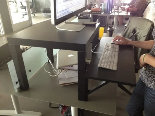
I don't know if people notice this in the background or in screenshots, but I use a 15" MacBook Pro for my benchtop computer. The battery failed, so it's always plugged into AC, now. It's now a flip-open desktop workstation, pretty much. I use this MacBook Pro to program microcontrollers and to have convenient access to the web and what not.

Our house is all Mac all the time. I have a Dell box used as a network storage server, but that's it. My regular desktop is a big-arse 27" 3.4 GHz iMac with a second 27" Cinema Display. Both are on wall-mount arms which are supposed to make my desk cleaner. However, as you can see in the photo below, all that's done is make more room for me to pile parts.

3.4 GHz iMac 27" with matching 27" Cinema Display over desk

Of course, what desk area would be complete with a jackalope and an oil painting of a monkey in a fez?

Repurposed Dell PC power supply as benchtop power supply

About my primary power supply... I took apart a my wife's old computer that she had when we met. It was a sad, sad old computer I'd given her to get her by that I think I salvaged from my uncle's office. The power supply makes for a fantastic DC power supply. It provides very clean and reliable 3.3VDC/14A, 5VDC/22A, and 12VDC/10A power. This was crucial when I was working with peltier devices, which drew more amperage at their ideal voltages than the digital power supply could give them. This Dell power supply doesn't even break a sweat when a peltier device asks for 3.5A. The max on my digital PS is only a little shy of 3A.

Temporary switch for Dell power supply

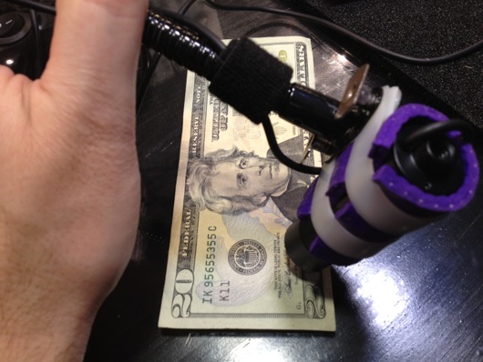
I turn the supply on or off using this little toggle switch I rigged into the main jumper for the power supply.When I become ambitious about really finishing organizing my bench, I will snip all the extra wires and connectors and clean up the power supply. I'm also going to extend the voltage and ground leads and put nice ends on them to make it easier to connect and disconnect them from my many breadboards. Speaking of...

Custom breadboard power supply adapter

I whipped together this little adapter so that I could quickly connect and disconnect the various voltage leads from the power supply to my breadboards. I quickly got tired of screwing and unscrewing the thumbscrews on the breadboards when I wanted to switch them out. Eventually, these connectors will be on-the-ready toward the back of the benchtop and the switch for the power supply will be mounted more conveniently. The power supply will be relocated up and out of the way. Right now, sadly, it sits on two pieces of wood on the ESD foam.

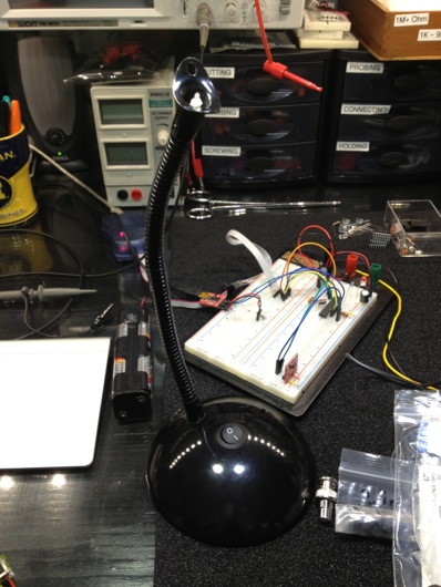
When I work with my favorite microcontrollers, the AVR series from Atmel, I don't usually use a proper Arduino board, even though I tend to use the Arduino IDE. Instead, I whip together a quick circuit with either a 16 MHz or 20 MHz quartz crystal on a breadboard. I usually have three or so of these setup and ready to tinker with. I do actually have a few different types of Arduinos I've purchased with gift cards, recently. Here's an example of a typical setup for me:

Quick AVR setup with supporting circuit on breadboard

I followed the recommendations from the ATmega328 datasheet for what components to put around it. There's a 10µH inductor on the analog voltage reference pin (in the photo above, it's on the Vcc pin, so ignore that). There's a 20 MHz quartz crystal on the XTAL1 and XTAL2 pins. Each of those pins is also connected to ground with 20 pF capacitors. Often times, I put a 7805 5V linear regulator on the + rails of ones side of the board and the other has either a 7812 12V regulator or LM10863V3 3.3V regulator on it. Of course, the proper capacitors near the regulators to clean up power are usually on there, as well. Don't forget the polarity diode so that you don't accidentally hook up the power supply leads backwards and cook something or popcorn an electrolytic capacitor.

As you can see from some of the above pictures and the one below, the edge closer to where I work on the glass surface gets cluttered with the parts I reuse the most.

Parts clutter on my ESD foam

About once every few months, I will clean up the area and put things back where they belong.

Field Notes® brand notebooks for diagrams and doodles

I keep my notes and diagrams and doodles in these awesome little Field Notes® brand notebooks with graph paper inside. They're about $10 for a 3-pack and each notebook has 48 pages in it. They're the perfect size to sit on the bench next to a project. Not so big that they require a lot of open space. Not so small that they're just not useful.

Last, but not least, I present my bourbon cabinet, complete with my hand-dipped (by me at the distillery) Maker's Mark® bottles. I have in my collection about 20 different bourbons. My goto at when we're out and about, of course, is Maker's Mark®. :)

That's it for the tour. If any of you have suggestions or comments, please, please leave them below in the comments section. I'd especially love to hear how you guys are storing your resistors. The ultimate trick still eludes me. I don't want to waste a little drawer for a single value, of course. Dividing up the drawers makes it too time-consuming to get one. I'm thinking along the lines of a Rol-O-Dex of resistors or something. I dunno. Comment away.

RoboStocking - AVR, Servo, Motor, IR Sensor, and BOOM!!! Merry Christmas!

At the office, we decided we were going to have a stocking decorating contest for Christmas. The rules were pretty lax, so I immediately thought of interactivity and electronics and blinky lights and whatnot. Well, that, and there was no way in you-know-what that I was going to hot glue glitter and spongy letters to a stocking with electricity being involved. Here is a video of the final product to pique your interest:

How did I do it? Easy. Some AVR programming (through my usual Arduino hackery) and some simple electronics and BOOYAH! Motion activated stocking with a Santa sign and some jingle bells.

First step was to make a framework to hold the mechanics and the electronics. I used plexiglass and Lexan to support the pop-up Santa sign and to act as the general body of the mechanical works inside the stocking. The layers of plastic were riveted together.

RoboStocking plastic frame and copper ribs

To push out the stocking into shape to make room for the guts, I took extra heavy gauge copper wire I had in my electrical drawer and used pieces of that for "ribs."

Heavy gauge copper wire as ribs

Copper rib bent 90º and riveted to main plastic frame

The sign was pushed up out of the stocking with a regular hobby servo and some armature work. The plastic worked as a track to keep in straight and sliding smoothly. The armature was made from parts used in RC airplanes I got at a hobby store.

Servo Santa sign linkage

The next thing was to make it motion sensitive. That was initially going to be controller by a PIR sensor, but it turned out to be too whacky. I settled on a nice little sensor by Sharp that I picked up at Sparkfun.com. They simply alter a voltage depending upon what's in front of the sensor and how far away it is. Really simple to experiment with and get a good idea of what numbers to expect from the ADC to trigger the action.

Sharp Long Range IR Proximity Sensor (2Y0A02)

I tried a number of methods for jingling bells. The first was funny, but a bit difficult to implement on the sticking itself. It involved a wheel (or plastic gear, in this case) and a rod with the bells hanging off of it. The idea was that the motor would push and pull the bells rapidly and make them jingle. It worked on the bench, but not in the stocking.

First attempt at mech-jingle bells

The ultimate solution I stuck with was simply a cam on a motor behind the bells. When it ran, it smacked the back of the front face of the stocking where the bells were hanging. It was essentially a big honking 12V phone vibration motor.

 Wood cam that vibrates jingle bells
Wood cam that vibrates jingle bells

Next step: Jingle bells. I tied them to the cheap Chinese-made stocking with thin copper wire as a sort of twisty-tie thing. Worked great. I wasn't very organized about where I put bells, just wanted to get a bunch in the general vicinity of the bell thwacker motor.

Jingle bells randomly stuck to the stocking's face

The brains behind all of this is, as usual, an AVR microcontroller. I use my own version of the Arduino IDE to upload firmware to my AVRs on the breadboard. The code is super simple. It basically just waits in a loop for the ADC to show a value from the IR sensor that meets whatever threshold I figgered out in my experiments with the sensor and ideal distances for triggering the sticking. When it gets a hit, it turns on the MOSFETs for the servo (the sign) and the motor (the bells). It start the motor spinning for hitting the bells and pushes up the sign. After a few alternating blinks of the [not-added-at-this-time] LEDs, it retracts the sign and stops the motor and cuts power to them both. That's pretty much it. Here's the RoboStocking motherboard:

RoboStocking motherboard with socket for ATmega328 microcontroller

I even put holly on the board in the etch. :) Because the wall wart that powers this thing outputs about 20VDC, I put a LM7805 5-volt regulator on the board for the logic stuff and another LM7805 regulator for the motor and servo. There was no reason to run the motor at its full 12 volts. It was only smacking the back of the stocking. There are two regulators because the power draw of the circuitry plus the motor plus the servo was causing the AVR to shutdown. Running on their own circuits gives them each the full power available through the individual regulators.

As always, I drew the circuit board in Adobe Illustrator, flipped it and printed it on my Samsung black and white laser. I've found that running the transfer paper through the laminator four times makes the toner really adhere to the copper without problems. I've notice that after four times, when you drop the board with the transfer paper stuck to it into the water bath, it dissolves off the board pretty quickly. The etch afterward is much higher precision, as well.

Board with printout of circuit to help me place components

The only thing left was to draw a cute sign for the slide-up. It took me a bit of trial and error, but I finally drew a decent cartoon Santa in my normal style and slapped a Christmassy looking font in the sign part of the slide-up thing. This setup makes it look like Santa is just hanging out in the top of the stocking. When he slides up, the actual sign is revealed below him, as if he's pulling it up for you.

Santa sign on RoboStocking

With everything assembled, the guts of RoboStocking look pretty cool:

RoboStocking with SantaSign and RoboGuts

What makes this story funny is that I was not able to finish this silly thing in time for our company Christmas party. I had to put the final touches on it over the weekend and bring it in the Monday following the party. It was met with great reviews, but could not win the contest that had past. :( Oh, well. There's always next Christmas. Sound and lights will be added, I assure you. ;)

AVR Serial Communications Using XBee RF Modules

I was contacted by Element 14 (Newark.com) recently about doing some product test drives using some of the products from their line card. I took two to three seconds to think about it. I know, tough one... XBee S2 ZigBee RF modules by Digi International

I have been chomping at the bit to use ZigBee wireless technology in a project. Digi International makes some REALLY cool and easy-to-use ZigBee RF modules that bring ZigBee technology down to a level that even I can implement without more than a few terse passes at a wireless book and a couple of datasheets. So, the first piece of loot I requested from Element14 was an XBee S2 module. I would love to link you to this module at Newark.com, but it appears to be gone. That is sad. BAck to our story... There was a spending limit on my test-drive loot. I ordered one XBee S2 module on my tab. The other XBee module was sent to me courtesy of Element14.com.

The ultimate project is based on a need at our house: We hang out on the back patio quite a lot and when we invite guests over, even after we ask them to just come on in, they ring the doorbell and we can't hear it out on the back patio. The leave disappointed that we would not be home when we said we would be. I'm kidding. Usually they do walk right in.

DIY remote doorbell using XBee modules

The first drawring I made used a brass marine-type bell with a string that was routed from the front door around to the back patio. Guests could simply tug on the string to get our attention. My wife wasn't keen on the network of pulleys and string required to make that happen. The drawring above is the watered down, no-fun-havin' version. Awe, who are we kidding? It's still fun. It's ALL fun! What's not to love about electricity and radio frequency waves making things do stuff??

Plan B for the remote doorbell is much cooler and much more electronic: Rig XBee to the house doorbell system so that it can signal a solenoid type of thing to plink a brass bell on the back patio. Not as Wallace & Gromit as the pulleys and string, but still pretty darn cool.

Oh, let me get this out early: Yes, übernerd, I know that XBee is overkill for a simple remote doorbell. The final version of this thing will use a simple little OOK (on-off key) RF module pair that simply sends on or off (button pushed or not). For now, though, this is a great way to get to know Señor XBee and his amigos.

Building Wireless Sensor Networks by Robert Faludi

Before I go any deeper into this project, I want to HIGHLY recommend a book on the subject of AVR/Arduino microcontrollers and ZigBee networks. If you're interested in this stuff, go out and get a copy of Building Wireless Sensor Networks by Robert Faludi, published by O'Reilly. I also highly recommend you do NOT do what I did: Do not buy the book, read it cover-to-cover, and do absolutely nothing hands-on. I wound up having to re-read large portions of the book again to get my bearings with the XBee modules from Digi. Try to have an AVR microcontroller (or Arduino) and a couple of XBee modules on hand when you start reading the book.

Now, the first thing I have to say about these modules is that they are stupidly simple to setup and get running, as you'll see in this post. I was asked to do a write-up by Element14.com and this is an easy one: These are AWESOME. There are plenty of sources on the Web for connecting XBee modules. I won't go into major detail, but I will show you how quickly you can get to AVR microcontrollers talking wirelessly with two Digi International XBee S2 ZigBee RF modules. Keep reading...

The process for getting two XBee modules talking, or, in this case, two AVR microcontrollers talking via XBee modules, it this:

  1. Get two XBee modules (Farnell.com part 1690810) and a handful of 10-pin, 2mm headers used to adapt the non-breadboard-friendly XBee pins to your breadboard
  2. Get one or two AVR microcontollers with UART capability (and supporting components) or one or two Arduinos
  3. Build cheesy adapters for the XBee modules so that they fit your breadboards
  4. Download the X-CTU Windows program to upload newer firmware and appropriate firmware to the XBee modules (this relates to setting up one XBee module as the "coordinator" and one as the "router" [see book above])
  5. Put some serial-savvy code on an AVR chip or Arduino and connect its UART pins to one XBee module's DIN and DOUT pins
  6. Connect the other XBee module's DIN and DOUT pins to a serial cable to your computer
  7. Send commands through the air to the AVR from your favorite terminal program

OK, that's oversimplified, but if you're comfortable with building circuits and working with Arduino or AVRs, that's all there is to it. Take a look at this setup in action (and please forgive the hastily shot and edited video):

If you're a Mac person, and I know I am, you're going to disappointed in the lack of a Mac firmware updater for XBee modules. However, it is pretty darn simple to fire up Boot Camp or VMware and update the radios the way the aforementioned book suggests. I just picked up my breadboard with the two radios and the AVR and the USB-RS232 cable and plopped it on my desk next to my iMac and fired up VMware and did it. Nice and easy, save for one issue: Once the upload of the firmware was complete, Windows XP Pro went to a BSoD (Blue Screen of Death). Pretty awesome. Let me say that it is no secret that I hate Windows. I'm disappointed in Digi for note having a Mac client to update firmware on the XBee modules. Maybe someday...

If you follow the book, you can get two AVRs or a computer and an AVR communicating in pretty short order. The code I wrote for the AVR to receive the serial commands from the computer to switch the traffic LEDs was easy and it actually worked the first time. It's really cool when stuff works as advertised.

If you've got some communicating you need to do between your microcontrollers, especially multipoint stuff, XBee modules are the way to go. Soooooo easy to setup and use. Head over to Newark.com or your favorite source for Digi International products and start mesh networking your DIY gadgets.

This post was originally about the remote doorbell idea. I'll write a separate post about that completed project using simpler RF modules from SparkFun, as ZigBee is WAY overkill for a remote doorbell, unless you're putting little remote bells or buzzers all over your mansion.