Subtitle: Electric Imp, Keep an Eye on the Bathroom, Would Ya?
iPotti #2 is the latest incarnation of iPotti, the custom bathroom availability monitoring system I built for my employer, meltmedia. I started designing and building the original iPotti in 2010 and it went into operation in early 2011. At the time, there wasn't anything like it that we were aware of. Lately, some other similar systems have popped up and their inventors have done some pretty cool stuff with them. I've found inspiration to reinvent iPotti. Plus, at meltmedia we'd like to use the device for marketing purposes in the near future.
Since 2011, meltmedia has outgrown its original office where iPotti ("number one") is installed. At that time there were about 20-some-odd meltmedians. Today, there are over 60 of us and we now occupy TWO different office spaces on the same campus. On the plus side, with the growth in the number of meltmedians came a growth in the number of pottis at meltmedia to service those meltmedians. On the not-plus side, there is only ONE iPotti #1 and it only watches TWO of the 9 or 10 pottis across two buildings. This situation needed to be rectumfied. [snicker]
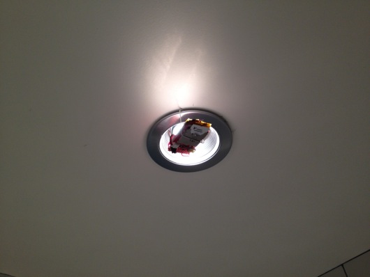
iPotti #2 is in the fully functional prototype stage. Stick it near a light or a door and BOOM! Pictured above you see the light sensing iPotti #2 prototype. It's not beautiful, but it works like a champ. I'm designing the new circuit board for the real thing right now, but I wanted to get this article out because what is working is pretty darn cool. I just couldn't wait. It's built entirely by parts purchased from one of my favorite sources, Sparkfun Electronics. Plus, it's a different approach to how status is broadcast to clients as compared to the previous version.
If I haven't mentioned it before in past articles, although I think I have, and this is a butt kissing moment... I love SparkFun and what they do. They make electronics much more accessible and fun for the casual to mid-level-loss-of-entire-weekends electronics peeps like myself. Their breakout boards and tutorials are a great way to get started or to just find help on your current project. I'm saying this because I really do love shopping there and I point people to them all the time. There are plenty of red PCBs in my projects and I have a giant stack of those famous red product boxes in my man cave.

The iPotti #2 Technology Stack
Both versions of iPotti have cool tech stacks, but they operate very differently. I'll touch on the hardware portion of the stack, first, then the software.
Hardware First
The original iPotti consisted of a central microcontroller (the now-defunct MAKE:Controller) that was hard-wired to the network and power (PoE: Power over Ethernet) and its two potti sensors were hard-wired to the main controller. Inflexible, to say the least; purpose-built.
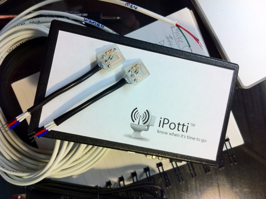
iPotti #2, on the other hand, is a distributed system: Each potti gets its own little battery-powered, WiFi-enabled ARM microcontroller with embedded sensor. The old iPotti main box was the size of a an old VHS videotape and had four wires coming out of it, whereas iPotti #2 remote sensors are EACH about the size of a Matchbox® car INCLUDING their rechargeable lithium ion polymer battery! The future is NOW and it's not very big, I can tell you.

Hello, Electric Imp! Meet iPotti #2!
At the core of every iPotti #2 sensor is an Electric Imp. The Imp is an amazing little piece of technology. I like them a lot. I'm not completely thrilled with the way they talk to the world, but it's workable. I'll get into that shortly. Here are the specifications on the Imp (from the datasheet for the imp001 [SD card-sized module]):
- 802.11 b/g/n WiFi
- 20MHz 11n channels, 1 x 1
- +16.75dBm max output power (802.11b)
- -97dBm typical sensitivity (1Mbps)
- Integrated antenna with 2.5dBi max gain
- 32-bit Cortex M3 processor
- Robust embedded operating system with fail-safe firmware updates
- Virtual machine for vendor firmware
- Embedded bi-color red/greenLED for status indication
- Embedded phototransistor for our patent-pending BlinkUp optical configuration technology
- 6 user selectable I/Os
- GPIO, PWM, Analog input & output
- SPI (2 channels), UART (3 channels), I2C (2 channels)
- Low power 6uA sleep mode
- FCC, CE, IC C-Tick certified
All that stuff is crammed into a little SD card package, BUT it is NOT a standard SD card. It uses its pins differently, so don't get any idears about plugging that thing into just any SD slot, although I believe it won't kill it, but don't quote me on that. K? K.
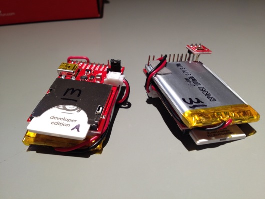
When you get a brand new Imp (and, from here on out, I'll be talking about the Developer's Edition, which is the one encased in an SD card form factor), the first thing you need to do is pop it into a suitable development board, like this one from Sparkfun, which is equivalent to the "April" board from the people at Electric Imp, based on notes in the schematic:
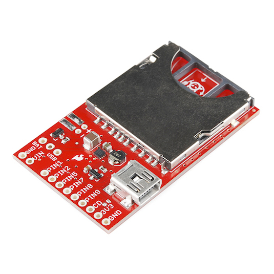
The board has a little ID chip on it that identifies the board to the Imp cloud. If you had a pile of Imp cards and swapped them in and out of the board above, they'd all run the same firmware while jacked into that board because the firmware is tied to the board, not the Imp plugged into it. If you build a device around that breakout board, the device itself get the firmware, not the Imp you plug into it. It's a cool set up. A little weird at first, but makes sense enough.
Once you have the Imp and the board ready and powered up, you have to commission the Imp using the BlinkUp app for your iOS or Android device. The BlinkUp app uses light pulses (blinks the screen rapidly, alternating black and white) to give the Imp the WiFi credentials it needs to work over the local network. Click on the link at the beginning of this paragraph to see how it's done, but it is very, very simple. Once the Imp has the WeeFees Creds, it can connect to your network and then out to the Imp cloud and get its firmware or simply start running if it's previously been flashed.
The Ambient Light Sensor
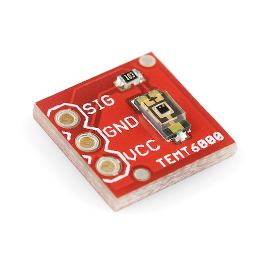
Again, as in the previous version of iPotti, I'm using the excellent little Vishay TEMT-6000 ambient light sensor. It's basically a photo transistor, but its responsivity to light is tuned to be similar to that of the human eye. Add a 10K resistor, connect it to an ADC on your project and read the voltage. It's that easy. It reads 0V in complete darkness to max volts in crazy brightness. In the case of the Imp, I hooked it to pin number 9 (and the 3V3 out and ground, of course) and I get from 0 to 65,535 for light. In the code, for now, I look for 5,000 as the threshold of dark and light. Less than 5,000 and the lights are off in the bathroom. Over 5,000 and the lights are on. Easy as pie.
The Power Source

For now, I'm using a 1,000 mAh polymer lithium ion batteries [again] from SparkFun (part number PRT-00339). It's turning out over time in testing that 1,000 mAh is probably a bit o'overkill, don't ya know. I've had the two prototype iPotti devices operating continuously for about over a month. The batteries at full charge were 4.2V (typical of these types of batteries) and I read them the other day and they were still at 4.16V. I'll get to how I'm saving so much battery juice in a little bit, but suffice it to say that I could probably put smaller batteries on these things and still get good longevity between charges.
The iPotti #2 Software
If you ask me, and I welcome you to, I'd say that the software was the hardest part to put together. Why? Go ahead, ask me... Because I hadn't done web app development in over 4-1/2 years. It's sad but it is true. I used to make my living doing it: I was hired on at meltmedia as a JavaScript guru. Pffft! No longer, I say! No longer. However, I've been relearning this new-fangled JS world and the latest HTML5 and CSS3 voodoo magic that's going on and I have to say that I love it. It's a bit weird coming from the Objective-C world, but it is fun.

The new iPotti software is based on a number of modern web technologies. On the server side, I wrote the RESTful-ish API on Node.js and the Express JavaScript framework. On the client side (the web app running in the browser), I use the AngularJS framework by Google and Twitter Bootstrap for UI components. To keep the status updates live while using the web app, I use the Socket.IO library. All that stuff and the Electric Imp cloud... thing... makes iPotti modern and real-time.
The Old
For historical reference, the original iPotti broadcast UDP packets across the network every two seconds. The software was a Mac OS X-only menu bar app that worked great, but wasn't very extensible and was really limited to only two potties. Here's what it looks like in action:

The "m" and "w" would turn red for busy, green for not-busy. It was a simple app and quite effective. I wrote it in Objective-C, the native language of Apple's OS X.
UDP is cool, don't get me wrong, but it isn't practical for the new-age, web-based applications that work over HTTP (which runs over TCP). The UDP packets for iPotti #1 were succinct and efficient in that they were tiny. They contained two characters: mw. If upper-case, the potti was in use. If lower case, then potti was available. Nice and simple. There was also a counter value after the "mw" to help clients know what order things were arriving in, since UDP is "connectionless" (it doesn't help you to keep packets in order and it doesn't guarantee the packets will make it from A to B at all). A typical packet looked like this inside: "mW 11847" which meant the "m" potti was available, the "w" potti was busy and there had been 11,847 packets broadcast since boot or it rolled over at some point. Where the UDP style of potti updating was inefficient was in the frequency and the uselessness of updates: Whether or not the potti was transitioning state from busy to available or vice versa, the iPotti #1 device was broadcasting packets to everyone every two seconds.
The New
iPotti #2 is uses websockets which run over HTTP (and, thus, TCP) which is a connection-based protocol: TCP helps you by guaranteeing that your packets and your data arrive in order and intact-ish (nothing is perfect 100% of the time, but that's the intent with TCP and HTTP). Socket.IO in the stack above keeps a connection alive between the Node.js server and the AngularJS client. Anytime an iPotti device sends an update to the server, the server then rebroadcasts that update message to the clients currently connected. The biggest improvement, though, is in the update frequency: iPotti #2 only updates clients when it needs to OR to let the server know that the device is still alive. For now, they devices are programmed to call home every two-ish minutes, regardless of the state of the potti they're watching. That's so there is at least some semblance of health monitoring for the devices. If the battery finally poops (pun intended, as always), the device won't report in and the server will grey out the indicator for that device. That's a cheap way of letting the person in charge of keeping the devices alive know that they might need to replace or recharge a battery. It might also let them know that the WiFi pooped out (yay potti puns!).
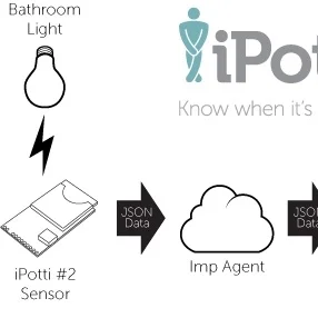
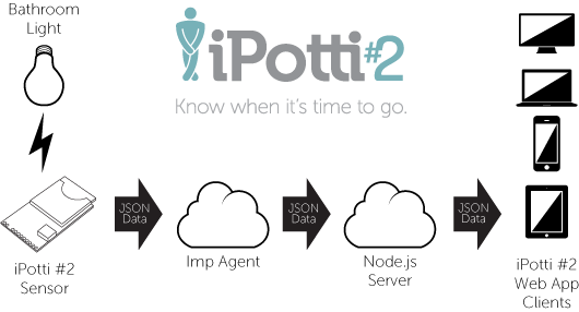
So, here's a rough diagram of the flow of things through the iPotti #2 system:
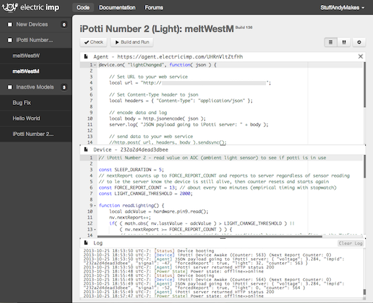
The old iPotti runs an RTOS on an Atmel AT91 chip and the firmware is written in C and uploaded from a special desktop-based IDE. For the Electric Imp, you write code for its firmware in the Squirrel language via the web-based Imp IDE at the Electric Imp developer website. In that same UI, you assign the firmware to the Imp boards via their unique ID or a name you give them (easier than remembering a crazy hexadecimal code). The Imps are sent their designated firmware from the cloud when they boot, if necessary. In the case of iPotti #2, I have one firmware for each type of sensor (so far, ambient light, motion, proximity and magnetic switch) and I have the ambient light firmware linked to TWO (as of today) Imp boards. The IDE looks like this:
In the "Internet of Things a la Imp," an Electric Imp talks to an agent in the cloud and that agent then does whatever you want with the data it gets from your Imp, like process it more, send it along or pour syrup on it. I dunno. You'll think of something to do with it. Personally, I'd rather the Imp communicate directly to my server. Maybe that's coming down the line. Not sure.
Anyhoo, in that screenshot on the left you find your devices that have been registered with the site. Any new, unregistered devices show up under, "New Devices." The section labeled, "iPotti Number..." is a list of devices that are registered for the "iPotti Number 2 (Light)" firmware. The "Inactive Modules" section lists all of the firmware modules I've written.
For iPotti #2, the "Light" firmware checks the ADC (to which the ambient light sensor is connected) every 5 seconds. If the light changes by a certain threshold, it wakes up the WiFi module and transmits JSON data to the agent. Otherwise, it won't bother burning battery on the radio circuitry and it goes back into deep sleep. When the agent gets data from an Imp, it sends that message (in JSON form) on to the iPotti Node.js server via its REST API. The Node.js server then broadcasts a modified version of that message (added fields) to the listening iPotti app clients. That's pretty much it.
I kept the Imp end of the system as simple as possible or the sake o the batteries. The brains-o-heavy-lifting-n-thinking are at the Node.js server piece. The server is in charge of determining things like the state of the client app indicators and whether or not an Imp has gone missing (not checked in in a while).
The Imp reports some other useful information back to the server besides it's light sensor reading, such as its voltage (which isn't really useful since the voltage is regulated to a pretty consistent 3.28V) and the WiFi signal strength. These little troubleshooting tidbits are useful for determining optimum WiFi coverage, among other things.
Below is a closer look at the Squirrel code that runs on the iPotti #2 Electric Imp devices:
The idea is to wake up from a deep sleep every 5 (production will be 10) seconds, check the ambient light reading, report it if it changes by a certain threshold and then sleep again. If the light doesn't change enough from the last check, don't waste power on the radio and just go back to deep sleep. If a few minutes have gone by and no changes have been observed, wake up the radio and report in anyway to let everyone know we're still alive and well. The following is the Squirrel code for the iPotti #2 Imp cloud agent:
At the agent end, all we're doing is receiving data from an Imp and forwarding it on to the Node.js server's REST API. That's it.
iPotti #2 Server and Web Pieces
If there is interest, I will write up a follow-up article about the Node.js & Company parts of this beast. It's sort of a whole other topic and, while it's an important part of this project, I'm not sure if I should get into how to setup a Node.js server. Plenty of people have done that a zillion times already.
While this wasn't a tutorial, per se, maybe it was inspirational enough to push someone down the path of web apps and Internet of Things. It's been a fun ride for me, for sure. If you have any questions, please feel free to comment.