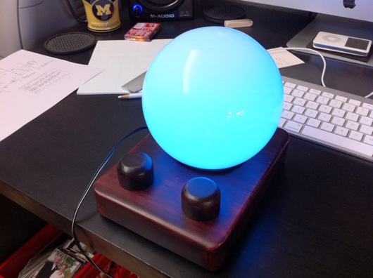
EDITOR'S NOTE: I've attached PDF files of the pentagon PCB and the motherboard PCB. If I had time to label them and make them pretty, I would, but this was never designed for mass production or consumption. Use at your own risk and frustration. For those with a short attention span, I give you a photo of the completed project (my biggest to date):
If you're interested in the story of this things, continue reading...
This idea came about randomly as a gift idea for my wife. I've built useless machines, clocks, etc. for other people (and myself), but hadn't built anything for my wife. I'm not sure what she's going to do with this thing, but it's the thought that counts.
Initially, this was just going to be a small little desktop thing with a few RGB LEDs on a circuit board with some kinda diffuser. Nothing fancy. Then, while walking through Home Depot, I found a frosted glass globe replacement thing for a wall sconce or lamp or something. It looked cool, wasn't too large, and screamed to have a bunch of LEDs stuffed inside it. I was at Home Depot for something else, of course, but I bought the globe, anyway.
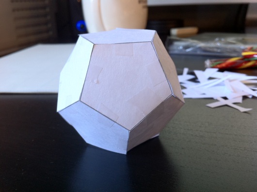
Next, I had to figure out how to illuminate the inside of this thing and make it do more than just cycle through colors. The first thing I did was devise a plane for the "bulb." I decided to go with a dodecagon, which I believe means a 12-sided object. Actually, I had no idea what one of these things was called. I just figured that I needed pentagons to make something more globe-like than a cube. I wanted light to emanate outward from this bulb thing like a light bulb, but with as few sides as possible. The sides were no doubt going to be PCBs, so the less complex, the better. Not that this wasn't one of the most complex circuit boards I've ever built in my short time as a hobbyist circuit builder. Here is the paper prototype:
I'm a visual guy, so I wanted to see this thing in real life and also make sure that it would fit into the opening of the frosted glass globe thing I bought. It did fit. I could handle pentagon-shaped circuit boards. The plan seemed doable.
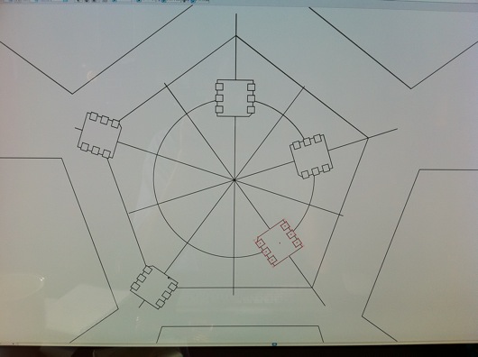
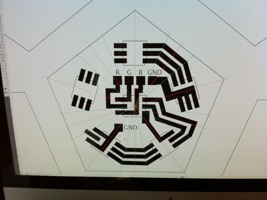
The next step was to plan out and print the pentagon LED panels for the bulb. As always, I use Adobe Illustrator to design the traces on my PCBs. I don't know if I've mentioned this in other posts, but I tend to lay the components for a project on the flatbed scanner and scan them in, then place them in Illustrator so that I have exact placements for through-holes and spacing on my homemade PCBs. So far, that idea has worked out swimmingly. The planning of a PCB in Illustrator looks like these next photos:
After I get the positions of the LED packages on the PCB, I need to connect them together and to ground, which on these panels were the edges, since they'd all be tied together at their corners. In hind sight, I would have gone the route of a common anode, not a common cathode. It would have been easier to control the individual colors with a simple N-channel MOSFET, as we'll see in a little bit.
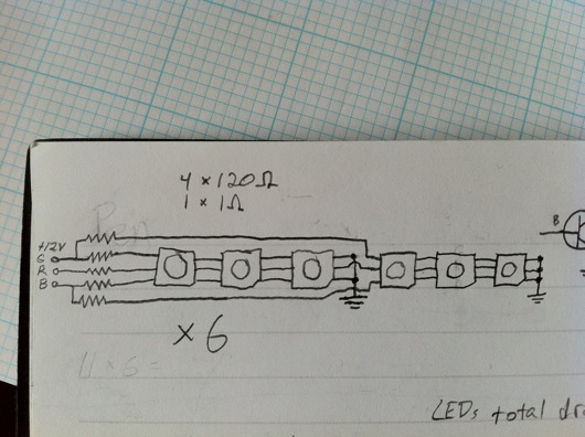
Like I did on the LED Reading Lamp project (so far, anway), I just worked out the best routes for the traces that would allow the three different colors to be connected in series. Since the red LEDs dropped less voltage than the greens and blues, all six red LEDs were able to be connected in series with a single 1 ohm resistor. The green and blue LEDs dropped enough voltage that I needed to break them up into sections of three LEDs, which meant a total of five series circuits on each panel. My sketch to figure this out looked like this:
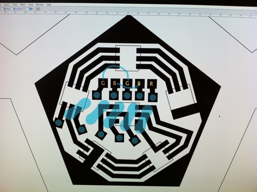
When the circuits were all tied together and the microcontroller and all other parts were together, the ammeter showed a maximum draw of only 270 mA. If it were for the 12 volts that drive the panels, I probably could have run this off a USB port. Oh, well. Back to our story... Here is the final trace design, including the location of the limiting resistors on the back side of the PCBs:
The blue resistor outlines show me where I need to place resistors on the back side of the panels. There are also two jumper wires for spanning out the second green and blue series circuits. I did that because I'm lazy and want to simply solder a 5-pin header through the back of the board. I can't fully explain why, at this juncture. It might have been late and I was tired. Who knows?
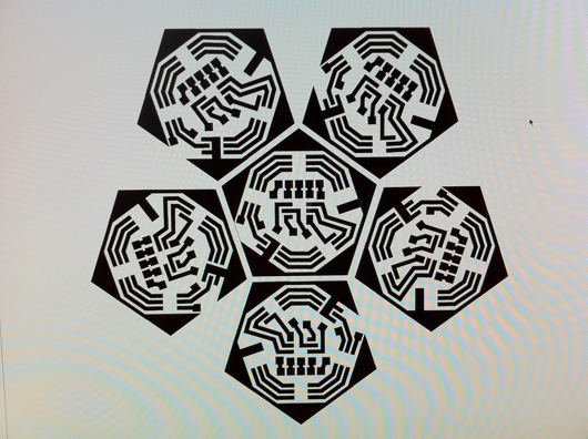
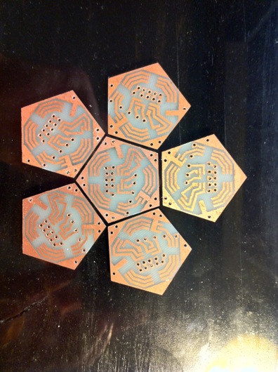
Finally, I duplicated the pentagon PCB design five more times and laid them all out so that I could print them together and use a band saw to cut them apart. The gap between the edges is enough for a band saw blade with a hair to spare for sanding and clean-up.
Here is the PDF of an LED petagon PCB: LED Pentagon Panel PCB in PDF form
As always, I used the toner transfer method to print and etch the boards.
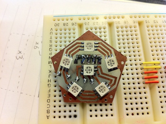
If you count the holes and the pads, I had a lot of soldering to do. A completed panel took me about 15 minutes, if my work area was prepped and the soldering iron was ready.
I don't know how ingenious this was, but after the Iron Man arc reactor thing, I needed a more efficient method of soldering SMD parts. My hands aren't steady enough to not flip the little parts off the board when the tip of the iron approaches. I stumbled onto poster gum at the grocery store and a light bulb went on. A super-tiny little ball of sticky poster hanging gum holds the part in-place perfectly and is non-conducting, so it becomes a permanent part of the board, but who cares? The solder looks 2.4 million times better than if I put a weight on the part or I just carefully attempt to get one leg soldered as an anchor.
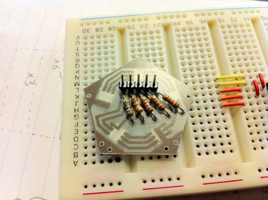
Here is what the back side of a panel looks like:
On the back, there is a 5-pin header, a single 1-ohm resistor for the red LEDs, and four 120-ohm resistors for each of the sets of green and blue LED circuits. The original thought behind the header pins was that I'd have lots and lots of time to make really nifty plug-in wires for the various panels and they's all converge on the motherboard of this thing for easy modular construction. That was dumb and painful. So I went the cheap and fast route and soldered wires all over the underside of the complete bulb and had just three wires come out for each color, plus a ground wire. Way easier, although soldering all those little wires was a royal pain.
One of these panels by itself was stupidly bright, so imagine what six were going to do:
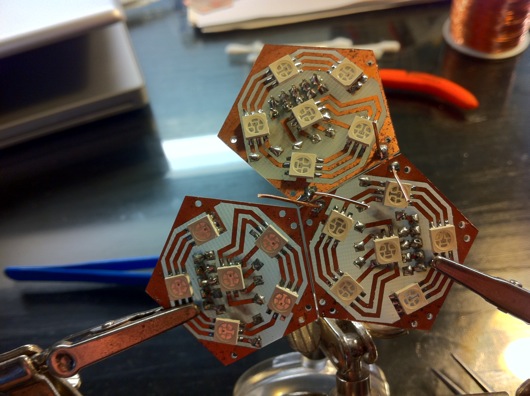
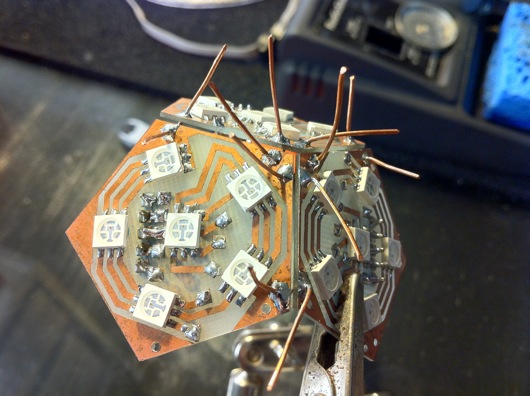
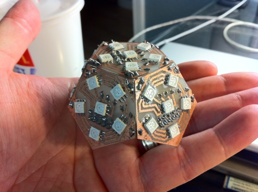
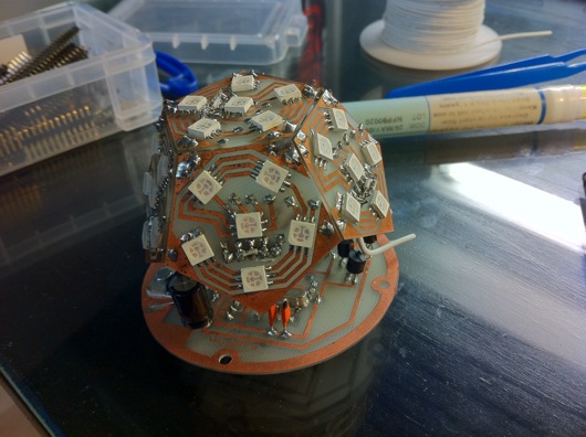
With all of the pentagon LED panels built, I had to "stitch" them together by their edges to bring all of their ground lines together. Here is a sort of sequence of the bulb being built:
I used bare copper wire to stitch the corners of the panels together. The extra wire was snipped off, of course.
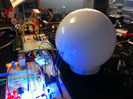
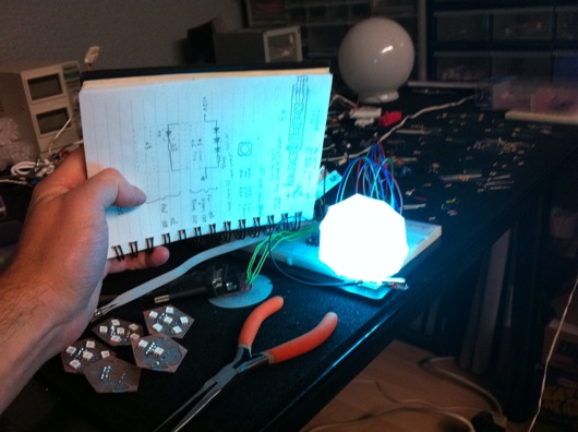
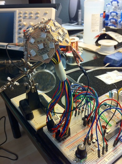
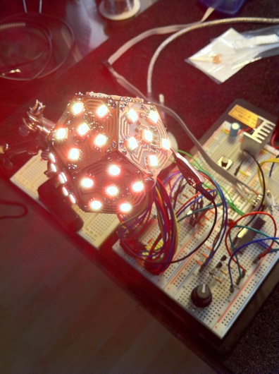
With all the panels stitched together, I had to connect together the color pins from each of them so that I'd have only one wire for each color coming out of the bottom. But, before I did that, I had to see this thing lit up on the breadboard. So, I created, "Squiddy" the LED bulb:
Lit up, Squiddy looked like this (which was toned down so that the iPhone 4's camera wouldn't freak out):
The bulb is powered with 12 volts, but controlled by pulse-width modulation via the Atmel ATmega168 microcontroller. A potentiometer controls the dimming of the LEDs. The other knob on the breadboard is a rotary encoder. This allows the user to change the mode of the lamp from a plain white for reading to an auto-cycling rainbow of colors to a user-selectable color. The built-in pushbutton changes the mode. The rotary encoder's knob changes the speed of the auto-cycling colors or the user-selected color.
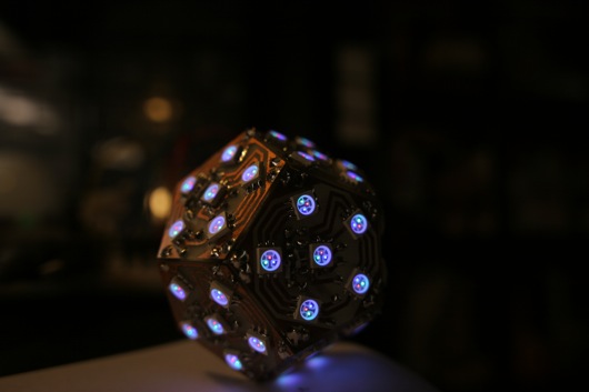
Here is a shot I took with my Canon 20D so that a photo could actually pick up the red, green and blue LEDs in the LED packages on the panels (which turned out to be a really cool artsy photo, to boot):
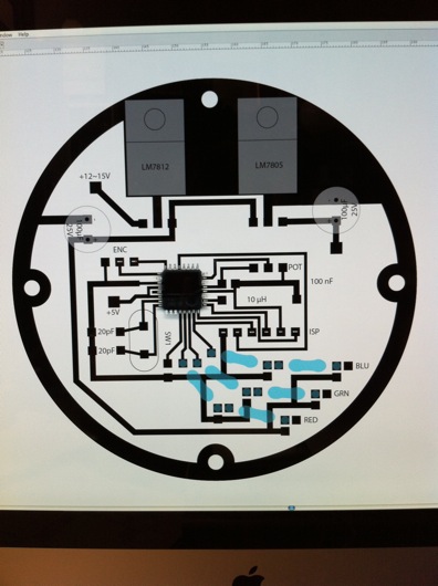
After all that, it seemed like this wasn't that large of an undertaking. Then I realized I hadn't even designed the motherboard OR the case. So, back to Illustrator to design the ROUND motherboard.
As always and as mentioned above, I scan the parts in and put them in the Illustrator document to be sure I get perfect alignment for everything. Yes, the datasheets have great specs for size and positions of pins and such, but I like seeing the parts next to each other on the screen in front of me. I usually put backside items in faint blue so I know where to put the through-holes to the front. This contraption is designed to run off a wall wart power supply, so it can MAYBE go a low as 12 volts (although my testing shows it prefers more) and as high as about 18 or so. 15 volts seems to be the magic number for many of the orphaned wall warts I have in my box-o-wall-warts. The diameter of the the board is about 5 mm shy of the opening of the frosted glass globe. The four screw holes were meant for stand-offs, but I wound up hot gluing a couple of little boards to the bottom of the PCB like table legs because I was antsy to finish it. Nobody see, nobody knows [click click].
Here is the PDF version of the motherboard PCB: Mood Lamp motherboard PCB in PDF form
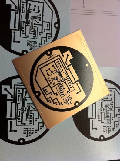
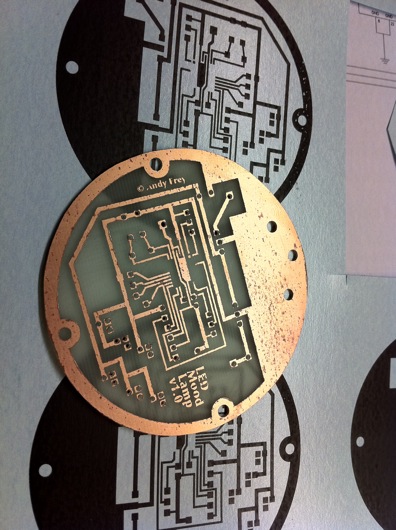
Toner transfer method means laser printing a reverse image of the traces onto shiny blue model decal-like paper and then heating that face down onto super-clean copper PCBs and then soaking in water until the paper lifts off to leave the toner on the copper:
It look AWESOME at this point, because I've started to run the paper and the copper board through the laminator FOUR times. I'm still getting a little pitting in the final etch, but the traces are generally plenty good for my projects. I'm considering trying the photoresist method to see if I can get higher quality edges on my traces.
Etched and drilled, this baby's ready for parts.
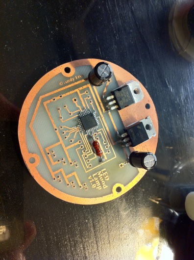
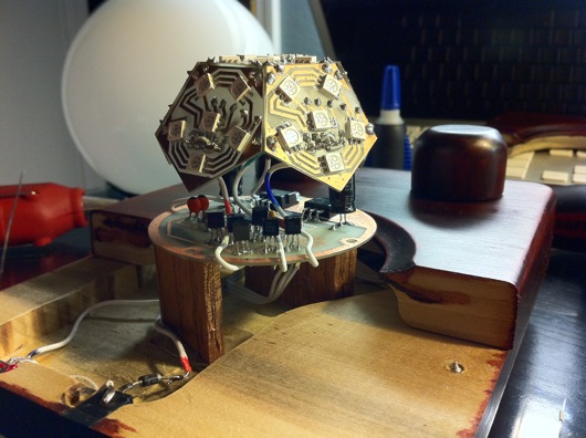
An LM7812 12-volt voltage regulator, an LM7805 5-volt voltage regulator, a couple of capacitors, an ATmega168, and an inductor, so far. With the rest of the parts and a few wires to suspend the bulb above the main board, the final main assembly looks like this:
Again, I felt good having completed this much work on the lamp. That good feeling didn't last long when I realized I had no concept for a case or buttons or anything else. Think, think, think... Ding! Into the garage!
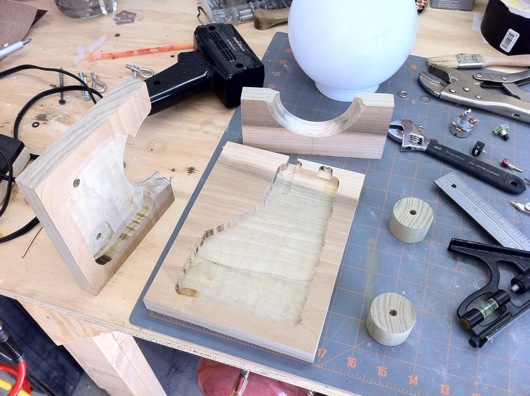
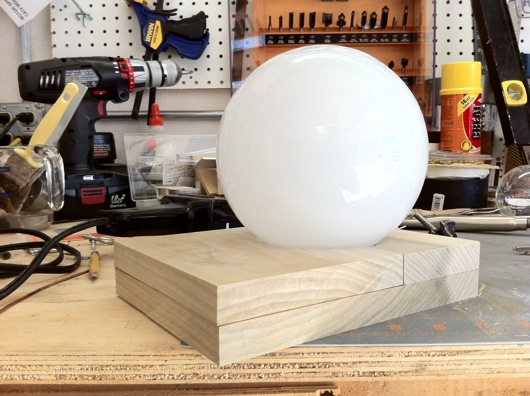
Some poplar, a little router action, a pinch of band saw, and BAM! Rough case:
The top piece of wood has a hole with a routed edge that will "grip" the flange on the glass globe. At the back of the lower piece of wood, I've notched out a place for the power plug and the power switch. The knobs were cut off a poplar dowel I had, for what I have no idea. Put together, the rough body of the case looked like this:
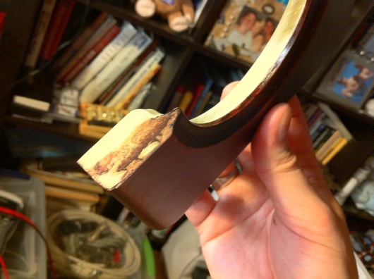
The stained/finished gripper groove looks like this:
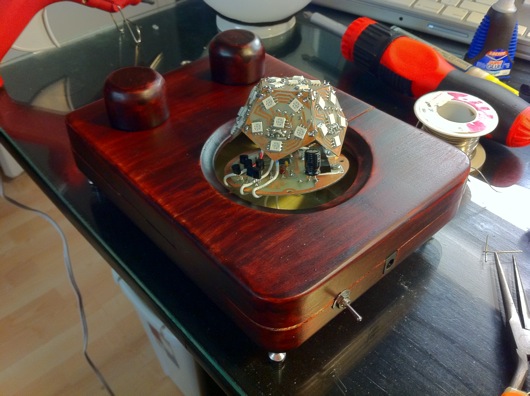
A test run of the fitting of all the parts and the case:
The knobs were just sitting on the front of the case. The main circuit assembly was kinda hovering in the opening. I had already hot glued the switch and power port into their respective slots. For added stability and wear protection, the power port was super glued, as well.
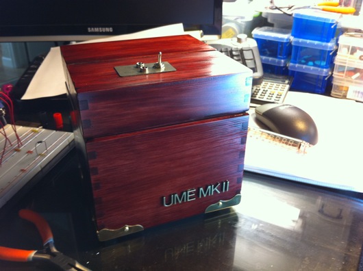
As for the final shape of the case, I used the band saw to round the corners. The rest was belt sander city. I sanded the ever living crap out of that thing to get all the sides and edges as smooth as possible. I use this 3X 320 grit stuff that really puts a fine finish on the wood prior to staining. The stain is the same stuff I used on the UME Mark II machines (Useless Machine Ever). It's a combination of stain and varnish that makes it really easy to put a nice color and shine on a finished wood product.
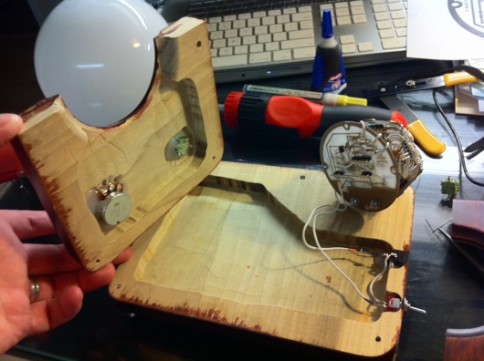
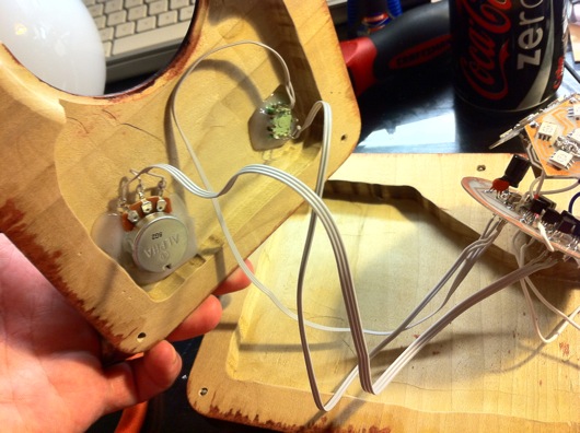
The interior of the case was routed out to allow the wires to go from the switches and knobs to the circuits:
The rotary encoder and the potentiometer were hot glued to beat the band. I'm medium-confident that they will not leave their posts.
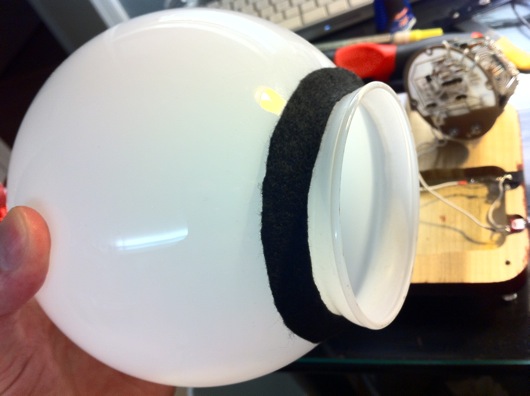
I cut out a little ring of felt to cushion the glass globe in its hole in the case. I don't know if it was necessary or if it will provide any protection, since we're dealing with a wooden case. Not like it's glass on steel or something. Eh, whatever. Looks swanky.
Next step: Wire up the controls to the main circuitry. I used strips from an IDE cable to keep it neat inside.
As I mentioned before, the main circuit board is standing on wood stilts held in place by hot glue. It's ugly, yes, but it's inside and it's plenty sturdy:
Here is a video of it functioning, albeit a little flaky, but good enough for government work:
