led

Charlieplexing LEDs with an AVR ATmega328

Charlieplexing LEDs with an AVR ATmega328

How many times has this happened to you? You have a little LED project with an AVR ATmega328 microcontroller (or Arduino) at its core and you need to light up a boatload.... A dingyload of LEDs. Maybe it doesn't happen a lot to you. It's happened on three recent projects for me. My latest two LED projects are a timekeeping piece that illuminates 21 characters from behind and a simple LED chaser thing.

As usual I wanted to keep the component count down on these projects. I also tend to prefer not to use a ton of ICs with busses between them and whatnot, if I can help it. So much darn soldering and stuff. Meh. Luckily, back in 1995, so the Wikipedia story goes, a super-smart dood named Charlie Allen at Maxim Integrated devised a super-ingenius way to control a large number of LEDs using a not-so-large number of microcontroller pins. The method is called, "Charlieplexing" and it seems a but daunting, at first, but it's not that bad once you figger it out.

LED Mood Lamp

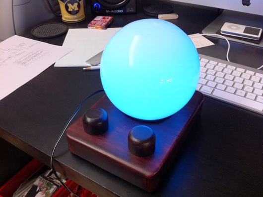
EDITOR'S NOTE: I've attached PDF files of the pentagon PCB and the motherboard PCB. If I had time to label them and make them pretty, I would, but this was never designed for mass production or consumption. Use at your own risk and frustration. For those with a short attention span, I give you a photo of the completed project (my biggest to date):

Completed LED Mood Lamp

If you're interested in the story of this things, continue reading...

This idea came about randomly as a gift idea for my wife. I've built useless machines, clocks, etc. for other people (and myself), but hadn't built anything for my wife. I'm not sure what she's going to do with this thing, but it's the thought that counts.

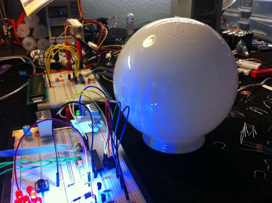
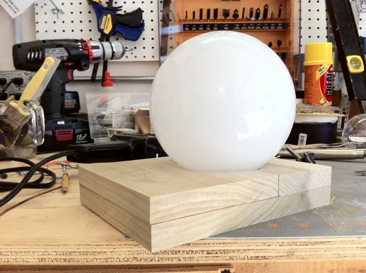
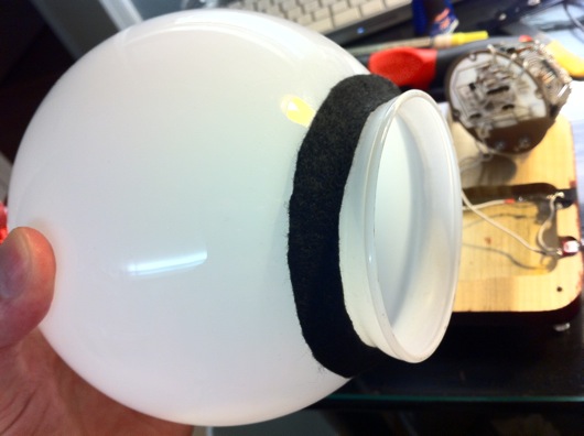
Initially, this was just going to be a small little desktop thing with a few RGB LEDs on a circuit board with some kinda diffuser. Nothing fancy. Then, while walking through Home Depot, I found a frosted glass globe replacement thing for a wall sconce or lamp or something. It looked cool, wasn't too large, and screamed to have a bunch of LEDs stuffed inside it. I was at Home Depot for something else, of course, but I bought the globe, anyway.

Frosted glass globe from Home Depot

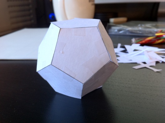
Next, I had to figure out how to illuminate the inside of this thing and make it do more than just cycle through colors. The first thing I did was devise a plane for the "bulb." I decided to go with a dodecagon, which I believe means a 12-sided object. Actually, I had no idea what one of these things was called. I just figured that I needed pentagons to make something more globe-like than a cube. I wanted light to emanate outward from this bulb thing like a light bulb, but with as few sides as possible. The sides were no doubt going to be PCBs, so the less complex, the better. Not that this wasn't one of the most complex circuit boards I've ever built in my short time as a hobbyist circuit builder. Here is the paper prototype:

Paper dodecagon prototype LED bulb

I'm a visual guy, so I wanted to see this thing in real life and also make sure that it would fit into the opening of the frosted glass globe thing I bought. It did fit. I could handle pentagon-shaped circuit boards. The plan seemed doable.

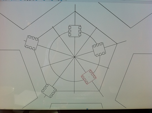
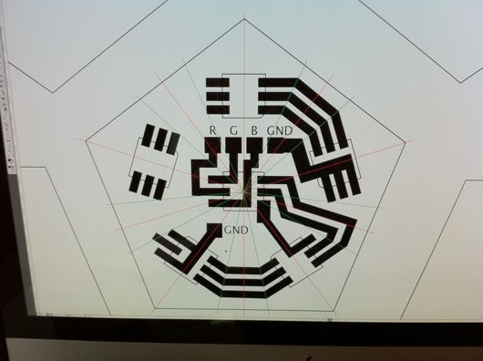
The next step was to plan out and print the pentagon LED panels for the bulb. As always, I use Adobe Illustrator to design the traces on my PCBs. I don't know if I've mentioned this in other posts, but I tend to lay the components for a project on the flatbed scanner and scan them in, then place them in Illustrator so that I have exact placements for through-holes and spacing on my homemade PCBs. So far, that idea has worked out swimmingly. The planning of a PCB in Illustrator looks like these next photos:

Evenly spaced SMD LED packages on a pentagon PCB

After I get the positions of the LED packages on the PCB, I need to connect them together and to ground, which on these panels were the edges, since they'd all be tied together at their corners. In hind sight, I would have gone the route of a common anode, not a common cathode. It would have been easier to control the individual colors with a simple N-channel MOSFET, as we'll see in a little bit.

Building traces on pentagon PCB

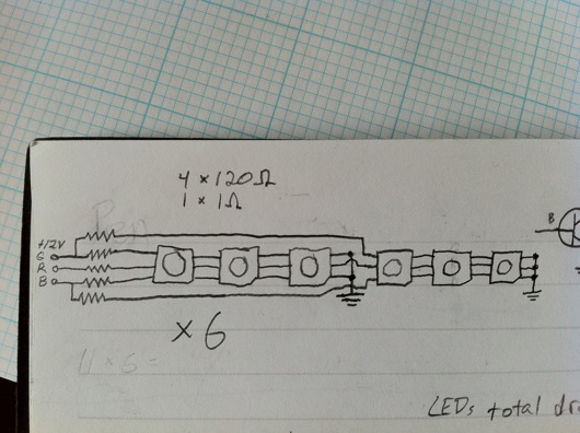
Like I did on the LED Reading Lamp project (so far, anway), I just worked out the best routes for the traces that would allow the three different colors to be connected in series. Since the red LEDs dropped less voltage than the greens and blues, all six red LEDs were able to be connected in series with a single 1 ohm resistor. The green and blue LEDs dropped enough voltage that I needed to break them up into sections of three LEDs, which meant a total of five series circuits on each panel. My sketch to figure this out looked like this:

LED circuit sketch

When the circuits were all tied together and the microcontroller and all other parts were together, the ammeter showed a maximum draw of only 270 mA. If it were for the 12 volts that drive the panels, I probably could have run this off a USB port. Oh, well. Back to our story... Here is the final trace design, including the location of the limiting resistors on the back side of the PCBs:

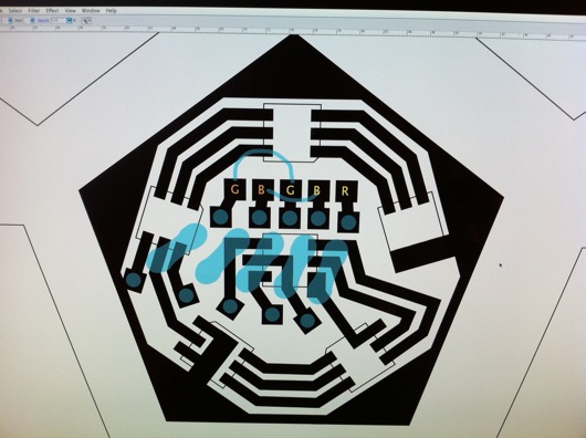
Completed design for pentagon-shaped LED PCB

The blue resistor outlines show me where I need to place resistors on the back side of the panels. There are also two jumper wires for spanning out the second green and blue series circuits. I did that because I'm lazy and want to simply solder a 5-pin header through the back of the board. I can't fully explain why, at this juncture. It might have been late and I was tired. Who knows?

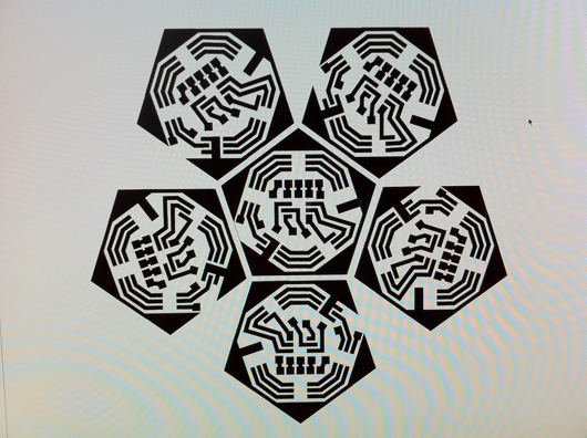
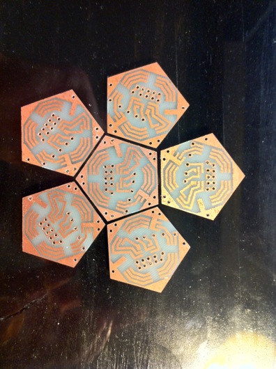
Finally, I duplicated the pentagon PCB design five more times and laid them all out so that I could print them together and use a band saw to cut them apart. The gap between the edges is enough for a band saw blade with a hair to spare for sanding and clean-up.

Top half of a dodecagon LED bulb PCB thing

Here is the PDF of an LED petagon PCB: LED Pentagon Panel PCB in PDF form

As always, I used the toner transfer method to print and etch the boards.

Printed, etched, cut, and sanded PCBs

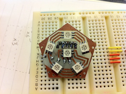
If you count the holes and the pads, I had a lot of soldering to do. A completed panel took me about 15 minutes, if my work area was prepped and the soldering iron was ready.

Front of completed pentagon LED panel

I don't know how ingenious this was, but after the Iron Man arc reactor thing, I needed a more efficient method of soldering SMD parts. My hands aren't steady enough to not flip the little parts off the board when the tip of the iron approaches. I stumbled onto poster gum at the grocery store and a light bulb went on. A super-tiny little ball of sticky poster hanging gum holds the part in-place perfectly and is non-conducting, so it becomes a permanent part of the board, but who cares? The solder looks 2.4 million times better than if I put a weight on the part or I just carefully attempt to get one leg soldered as an anchor.

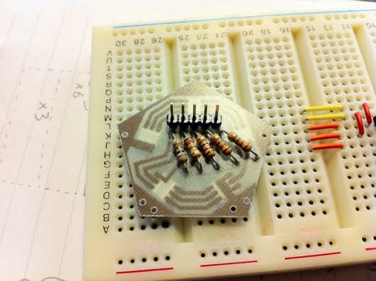
Here is what the back side of a panel looks like:

Back of completed pentagon LED panel

On the back, there is a 5-pin header, a single 1-ohm resistor for the red LEDs, and four 120-ohm resistors for each of the sets of green and blue LED circuits. The original thought behind the header pins was that I'd have lots and lots of time to make really nifty plug-in wires for the various panels and they's all converge on the motherboard of this thing for easy modular construction. That was dumb and painful. So I went the cheap and fast route and soldered wires all over the underside of the complete bulb and had just three wires come out for each color, plus a ground wire. Way easier, although soldering all those little wires was a royal pain.

One of these panels by itself was stupidly bright, so imagine what six were going to do:

A single pentagon panel under the paper dodecagon

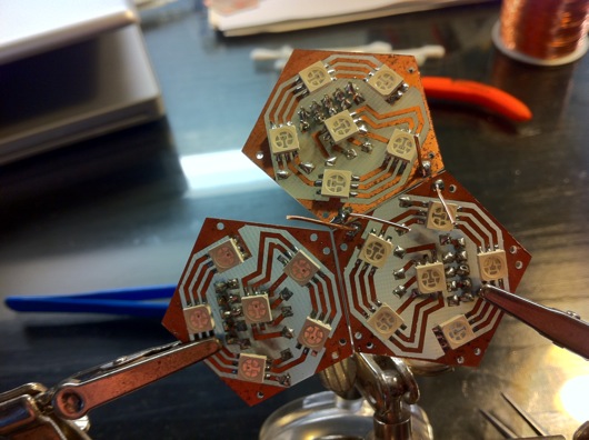
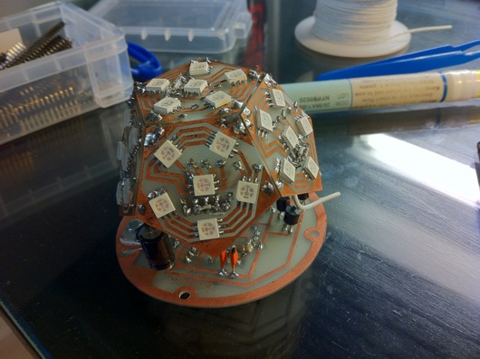
With all of the pentagon LED panels built, I had to "stitch" them together by their edges to bring all of their ground lines together. Here is a sort of sequence of the bulb being built:

Panels being stitched together with copper wire

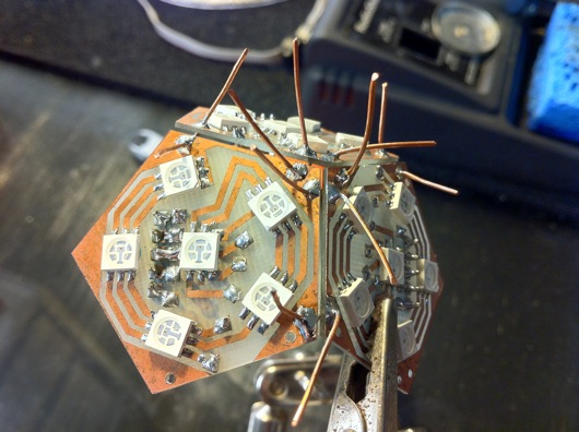
I used bare copper wire to stitch the corners of the panels together. The extra wire was snipped off, of course.

Panels being stitched together with copper wire

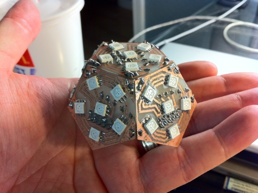
Completed LED bulb

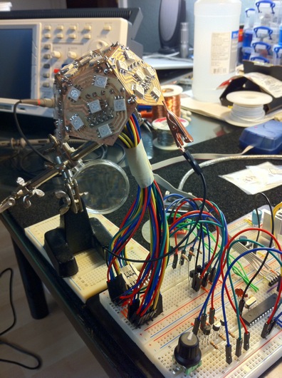
With all the panels stitched together, I had to connect together the color pins from each of them so that I'd have only one wire for each color coming out of the bottom. But, before I did that, I had to see this thing lit up on the breadboard. So, I created, "Squiddy" the LED bulb:

Squiddy the LED bulb

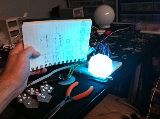
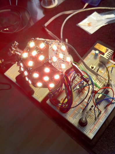
Lit up, Squiddy looked like this (which was toned down so that the iPhone 4's camera wouldn't freak out):

Squiddy lit up

The bulb is powered with 12 volts, but controlled by pulse-width modulation via the Atmel ATmega168 microcontroller. A potentiometer controls the dimming of the LEDs. The other knob on the breadboard is a rotary encoder. This allows the user to change the mode of the lamp from a plain white for reading to an auto-cycling rainbow of colors to a user-selectable color. The built-in pushbutton changes the mode. The rotary encoder's knob changes the speed of the auto-cycling colors or the user-selected color.

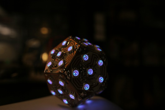
Here is a shot I took with my Canon 20D so that a photo could actually pick up the red, green and blue LEDs in the LED packages on the panels (which turned out to be a really cool artsy photo, to boot):

Cool DSLR shot of LEDs on bulb

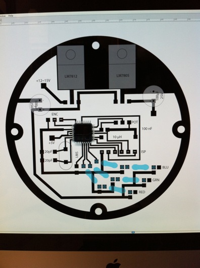
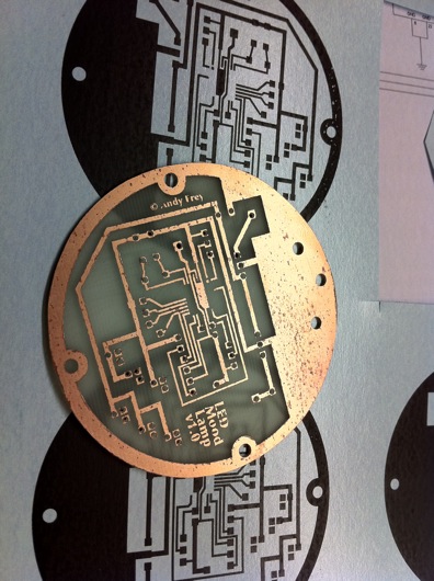
After all that, it seemed like this wasn't that large of an undertaking. Then I realized I hadn't even designed the motherboard OR the case. So, back to Illustrator to design the ROUND motherboard.

Motherboard design in Illustrator

As always and as mentioned above, I scan the parts in and put them in the Illustrator document to be sure I get perfect alignment for everything. Yes, the datasheets have great specs for size and positions of pins and such, but I like seeing the parts next to each other on the screen in front of me. I usually put backside items in faint blue so I know where to put the through-holes to the front. This contraption is designed to run off a wall wart power supply, so it can MAYBE go a low as 12 volts (although my testing shows it prefers more) and as high as about 18 or so. 15 volts seems to be the magic number for many of the orphaned wall warts I have in my box-o-wall-warts. The diameter of the the board is about 5 mm shy of the opening of the frosted glass globe. The four screw holes were meant for stand-offs, but I wound up hot gluing a couple of little boards to the bottom of the PCB like table legs because I was antsy to finish it. Nobody see, nobody knows [click click].

Here is the PDF version of the motherboard PCB: Mood Lamp motherboard PCB in PDF form

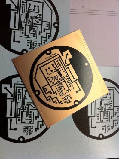
Toner transfer method means laser printing a reverse image of the traces onto shiny blue model decal-like paper and then heating that face down onto super-clean copper PCBs and then soaking in water until the paper lifts off to leave the toner on the copper:

Toner transfer of main circuit board

It look AWESOME at this point, because I've started to run the paper and the copper board through the laminator FOUR times. I'm still getting a little pitting in the final etch, but the traces are generally plenty good for my projects. I'm considering trying the photoresist method to see if I can get higher quality edges on my traces.

Etched main circuit board

Etched and drilled, this baby's ready for parts.

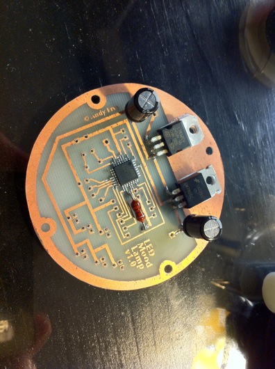
Added a few parts to the board

An LM7812 12-volt voltage regulator, an LM7805 5-volt voltage regulator, a couple of capacitors, an ATmega168, and an inductor, so far. With the rest of the parts and a few wires to suspend the bulb above the main board, the final main assembly looks like this:

Final main circuit assembly for LED Mood Lamp

Again, I felt good having completed this much work on the lamp. That good feeling didn't last long when I realized I had no concept for a case or buttons or anything else. Think, think, think... Ding! Into the garage!

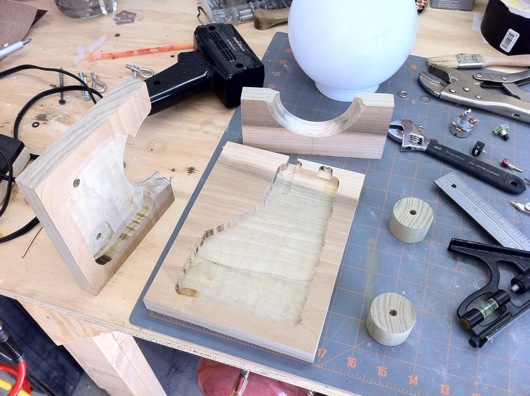
Some poplar, a little router action, a pinch of band saw, and BAM! Rough case:

Rough case routed out of 3/4" poplar

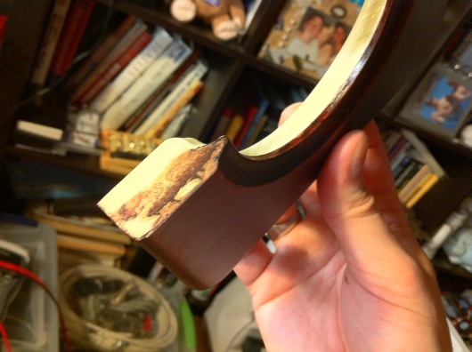
The top piece of wood has a hole with a routed edge that will "grip" the flange on the glass globe. At the back of the lower piece of wood, I've notched out a place for the power plug and the power switch. The knobs were cut off a poplar dowel I had, for what I have no idea. Put together, the rough body of the case looked like this:

Rough case sans knobs

The stained/finished gripper groove looks like this:

Groove that holds glass globe

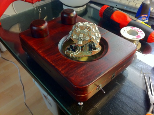
A test run of the fitting of all the parts and the case:

Test fit the parts and the case

The knobs were just sitting on the front of the case. The main circuit assembly was kinda hovering in the opening. I had already hot glued the switch and power port into their respective slots. For added stability and wear protection, the power port was super glued, as well.

As for the final shape of the case, I used the band saw to round the corners. The rest was belt sander city. I sanded the ever living crap out of that thing to get all the sides and edges as smooth as possible. I use this 3X 320 grit stuff that really puts a fine finish on the wood prior to staining. The stain is the same stuff I used on the UME Mark II machines (Useless Machine Ever). It's a combination of stain and varnish that makes it really easy to put a nice color and shine on a finished wood product.

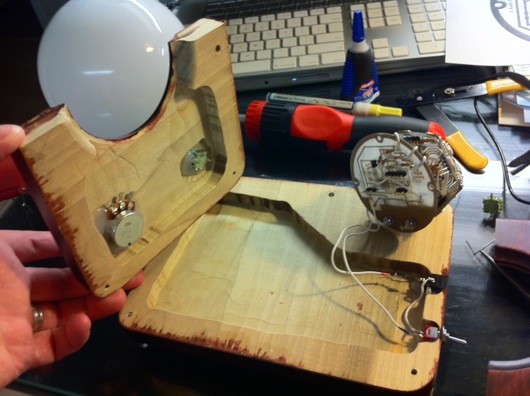
The interior of the case was routed out to allow the wires to go from the switches and knobs to the circuits:

Inside of case with space for wires

The rotary encoder and the potentiometer were hot glued to beat the band. I'm medium-confident that they will not leave their posts.

A little felt cushioning for the glass globe

I cut out a little ring of felt to cushion the glass globe in its hole in the case. I don't know if it was necessary or if it will provide any protection, since we're dealing with a wooden case. Not like it's glass on steel or something. Eh, whatever. Looks swanky.

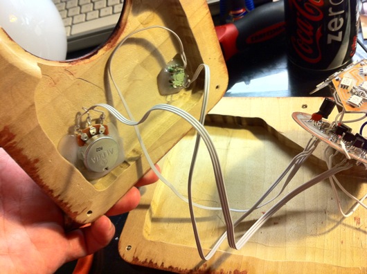
Next step: Wire up the controls to the main circuitry. I used strips from an IDE cable to keep it neat inside.

Wiring for controls

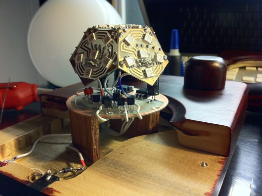
As I mentioned before, the main circuit board is standing on wood stilts held in place by hot glue. It's ugly, yes, but it's inside and it's plenty sturdy:

Wood stilts for main circuitry

Here is a video of it functioning, albeit a little flaky, but good enough for government work:

Hack the SparkFun Big Red Dome Button!

Needs more shine! The light bulb inside is medium OK in its ability to attract insects and people with ADD, but I wanted a little better (not too much, though). I also wanted signage. This is a super-simple project that anyone with even questionable soldering skills can pull off. Plus, there is enough room behind the red part of the button to put most any LED you like. Finished Dome Button Upgrade: Lower power, better

First, let's start with what the awesome big red dome button from SparkFun looks like as shipped:

SparkFun Big Dome Pushbutton as shipped

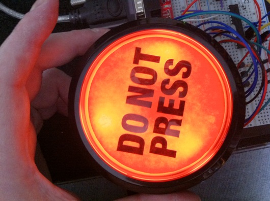
Eet's Oh-Kay. What's more fun than a big-honkin' red button?? It could wind up as a History Eraser button like on the 90's cartoon Ren & Stimpy. Maybe a self-destruct button? I'm going to make something similar to the button from the movie The Box. Nice wooden case, flip-open lid, big lettering that reads, "DO NOT PRESS" and pulsing backlighting. How can you NOT press a button like that? When the button is pressed, it will play Daffy Duck going nuts.

Here is the original light bulb lit by 12 volts AC:

Original light bulb for dome pushbutton

It's OK and looked decent behind the red dome, but it draws a bit of power and it's old fashioned and not as neato as LEDs.

We start by flipping over the button and checking out what we have to work with.

Under the dome button

We need to take this thing apart to the point that we have all the pieces sitting on the desk, ready to be upgraded. The switch and light assembly twists to unlock and then pulls out of the center of the button.

Switch and light assembly

Next, pull out the lightbulb from the assembly. It simply pulls out. Just tug on it, maybe wiggle it a bit, and it will come out eventually.

Light bulb removed from switch assembly

Unscrew the big white plastic nut from the back of the button to release the main part of the dome button from the bigger black base thing. You'll be left with the basic parts and you can display them neatly like I did:

Fully disassembled big dome button

To release the top red part of the button, the dome, from the whole thing, you need to squeeze the little white tabs inside the center of the button where the switch and light assembly was.

White tabs in center of button hold top in place

Once that red dome part of the button is loose from the black base, you can pry the red off the white with a little screwdriver or other similar implement in order to get to the pulp and juice of the fruit. What?

Prying open the red dome

Now we have access to the disc inside the red dome to which we can affix signage.

Inner sanctum of dome button

I took a quick measurement of the white disc and fired up Adobe Illustrator (which I also use to create my circuit board designs) to make the appropriate sticker. I printed the words on full-sheet sticky-backed laser printer paper, available at many places. If you can't find it, this project is probably over your head.

Warning label for dome button

For this hack... I mean, upgrade, we're using my favorite little SMD LEDs from SuperBrightLEDs.com, or pick your favorite supply source. They have three little white LEDs in a single, easy-to-solder surface-mount package. I've used these many times for projects like the Iron Man arc reactor, the LED reading lamp, and a new project about to be posted (you'll have to check back to see it).

5mm triple white LED SMD package

Two things happened in this next step and I forgot to photograph the process, but I took a strip of IDE cable and peeled a section of three wires from it. I then placed that three-conductor cable and placed it inside the perimeter of the white part of the button where the light bulb used to shine through. I marked it to the length of the inner circumference of the white thing. I then divided that by 3 and chopped it in the two spot and trimmed back the insulation on each of the ends of the cables. I then soldered each of the three LEDs in each of the three SMD LED packages in series. Basically, I just daisy-chained the LED packages together. At one end, I soldered a single, 22 gauge wire to the cathodes of the LED package. On the other end, I soldered another 22 gauge wire to the anodes of the LED package. Look at the second photo of the interior of the dome below.

I lined the inside of the dome with sticky-backed foil, which I picked up from Home Depot. It's in the plumbing and heating section and they use it to seal and for reflective insulation, I think. All I know and care about is that it makes a great reflective surface for scattering light. I used it in the Man Cave lighting upgrade  and 12 VAC power supply project.

Dome button lined with sticky foil

Here is a closer shot of the LEDs and the IDE cable:

Notice the LEDs cabled together

The foil tape holds everything in place. The positive and negative leads then are routed out through the hole in the center where the light bulb used to be located.

As always, I marked the leads for positive and negative.

Leads marked with black/red

And here is the main part of the button put back together:

Reassembled dome part of button

Now, put the dome assembly back into the black holder and put the spring back:

More put back togetherness

Next, we need to prepare the switch thing a bit. The brass clips inside the switch holder need to be removed. We don't need them at all. You could solder the leads from the LEDs to the brass thingy, but I didn't. Use a small screwdriver again to pry the side away from the switch. There is a notch that the plastic snaps into on the switch. Once you pry that away, the plastic holder will slide off the switch easily.

Pry off plastic switch/bulb holder

Next, remove the brass clips. They will be bent pretty well in the process. Doesn't matter. We don't need them.

Brass bulb clips removed

Route the leads through the plastic switch holder and twist it back into the button.

Route leads and reinsert holder

Next, route the leads out the sides of the holder so that the switch will snap back into place.

Leads out the sides, switch back in place

Connect the leads to your 12-volt DC power supply with a limiting resistor (depends on your LED specs) and it should light right up!

Viola! Lighted and customized big red dome pushbutton!

Update: LED Reading Lamp Materializing

For those of you with short attention spans, like me, here is a quick and lame video I threw together in iMovie:

I am building this for the new awesome bed I will be building this winter for our bedroom. There will be two of these lamps, one for me and one for my wife on either side of the headboard. The LED head will have a metal (or whatever I end up finding) shroud on it to keep light pollution down to a dull roar for the other person who might be sleeping.

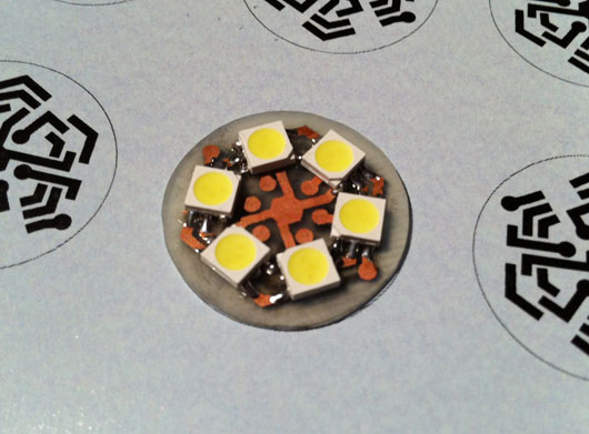
The previous post showed the traces for the printed circuit board I made. Here is a photo of the board with the six surface-mount triple-LED packages soldered into place:

LED Head PCB

Each of those white squares has three über-bright white LEDs in the yellow stuff. I designed the circuit board to connect one LED from each of three SMD packages at a time, thinking I might use that layout to better dim the whole lamp head. Turns out, that circuit layout just makes for a really cool-looking circuit board.

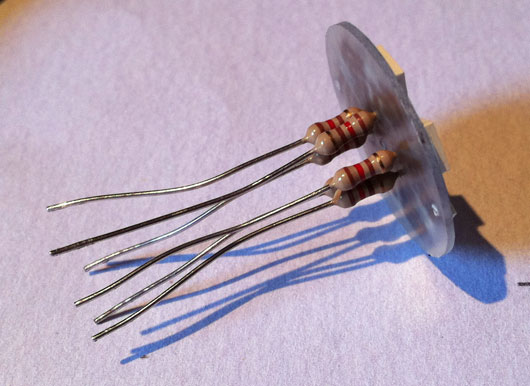
Here is a photo of the underside of the LED lamp head with the resistors for each set of three LEDs in series:

Resistors on back side of LED head

There are three holes left, as of that photo, which will have the ground wire connected through and soldered. Each set of three LEDs and their resistor will have 12 volts supplied to them which will be controlled by a 3904 PNP transistor which itself will be controlled by the AVR microcontroller. The transistor will act as a switch for the pulse-width modulation provided by the microcontroller.

For those who aren't sure what pulse-width modulation is, the short story is that it is super-fast on and off switching. It's fast enough that you do not see a flicker. We use PWM to dim LEDs because they do not work efficiently without a specific voltage being given to them. So, we flicker the voltage that the LED likes really fast and emulate dimming. For each "flicker" of the switch, the amount of time that flicker lasts can be divided between on and off. The more on time we give the LED, the brighter it looks. The more off time, the dimmer it looks. Weird, yes. But, that's the right way to do it. PWM also works for DC motors and such. Discussion for another time. Maybe that's a discussion for someone who was properly trained in all this. I know enough to be dangerous, even though I try to be safe at all time.

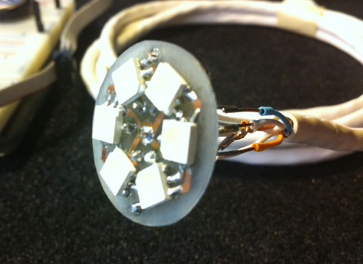
LED Head on power cable

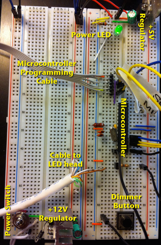
The cable carries six +12VDC wires and two ground wires to the back of the LED lamp head. The other end is currently plugged into the breadboard prototype of the controlling circuit. Here is the breadboard and labels for the various parts:

Breadboard of LED reading lamp

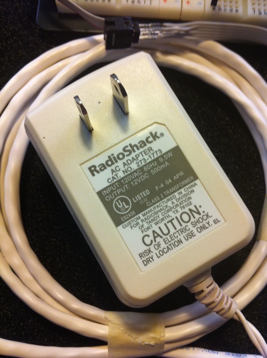
The power for the whole shindig is provided by a spare "wall wart" power supply, like the ones that power your TV boxes or network routers or wireless home telephone base stations. Here is the actual one I'm using, the end of which I snipped off to be able to plug its wires into my breadboard:

12V Power Adapter

These silly things provide pretty craptastic power, as far as DC circuits are concerned. They pretty much always supply a voltage other than what the label reads. This particular one measure out at 15 volts. Voltage to spare, baby! What's important is how much power (amps) we need to draw from the thing. Our circuit cannot pull more milliamps from the adapter than it is labeled to be able to supply. Luckily for this little project, we're only drawing at maximum about 91 milliamps. Not much at all, considering we're powering 18 super-bright LEDs and a little computer-on-a-chip. The Radio Shack adapter I'm using provides up to 500 mA of current. We're good.

The Atmel AVR microcontroller (the model is an ATmega328P, which is complete overkill for this, yes, but I didn't feel like reconfiguring my customized Arduino IDE to work with one of my little 8-pin ATtiny chips) basically sits and waits for the pushbutton to be pressed. When it senses a press, it delays for 25 milliseconds to keep the switch from bouncing on and off (a thing called, "switch bounce"), then gradually fades the LEDs up to the next brightness level. When it hits the last level, the next button press will shut off the LEDs.

Hope you found that one interesting!

Tony Stark for Halloween 2010: The Arc Reactor (RT Mark II)

UPDATE: Want a PCB and components for your own project? I've had a deluge of requests for the PCBs for this project. If you're interested, please contact me through this blog. I'm trying to figure out whether it's worth it to sell the boards alone or maybe as a kit with the LEDs and resistors (or current limiting devices) or maybe even assembled (LEDs, resistors and power leads). I have been dying to post photos of my latest colossal time-sucker-of-a-project: My Halloween 2010 costume is Tony Stark. Iron Man would have been a pain in the mechanical arse, but Tony Stark's only challenge is that crazy super-glowy round life-saving thingy thing in his chest which is visible under a shirt. This is the most ridiculous and complicated build I've done to date.

This post is about building the arc reactor Tony Stark needed to survive in the Iron Man movies. The particular version I wanted to build was the RT Mark II, which Tony built in his home lab once he got home from his captivity in the desert. It's more refined than the first version he built in the cave and every bit as swanky. Mostly, I liked the look of the second one better, myself. The one I'm talking about can be seen in the movie fairly up-close when Pepper Potts has to remove the old one and replace it with this new one.

So, first thing's first... I had to create a round circuit board (and a circuit, for that matter) with some super-bright LEDs that wouldn't catch fire under my shirt and, at the same time, would be visible from space from under my shirt. Ideally, I wanted this thing to stay fairly bright for as long as possible, like, say, a long night at a Halloween party. I'm just sayin'... I shopped around at SuperBrightLEDs.com and found some 5mm square surface-mount LEDs. These little doods have THREE little ultra-bright LEDs in each little 5 mm X 5 mm X 1.5-ish mm package. The blue ones that I used in the were so bright that when properly powered, they left greenish-yellowish spots in my vision for a while after looking at them.

I wanted the PCB to be functional, of course. It needed to properly connect the parts of the circuit together. But, I also wanted the traces to look movie-like. Busy, complex, important, and artsy at the same time. I design the circuit in Illustrator and tried my best to make the traces look like they were more than just power for LEDs:

Circuit board plans

You can see that the PCB design even includes the Stark Industries logo at the top. The zig-zaggy parts are the landing pads for the SMD LED packages. They have three anodes on one side and three cathodes on the other. I ran each SMD LED package's individual LEDs in series. There are 14 total SMDs, or 14 total three-LED series circuits. Each of the 14 series LED circuits connects to the ground bus (the outer ring in this design) and +9.6 volts via the center "C" ring. The little squares are the through-holes for the 15-ohm resistors for each of the 14 SMDs. The final etched board looks like this:

Finished etched printed circuit board

The fuzzy edges and weird texture on the traces are due to some craptastic refurb toner cartridges I bought for our HP 2600n color laser printer. The black cartridge deposits a funky pattern of toner all over the page. This translated to the pattern being transferred onto my PCB. To make PCBs, BTW, I use the toner transfer method. The products I use are from Pulsar and their stuff works AWESOME. I never imagined I'd be able to create my own circuit board this easily and with such accuracy. I bought the laminator they recommend using. The laminator came in handy for the our badges to the 2010 Stark Expo:

Fake official Stark Expo 2010 badges laminated

I am going as Tony Stark, including growing a goatee and moostash:

Me, er, Tony Stark

My wife is going as Pepper Potts and coincidentally looks just like her.

Here is the completed board with parts populated:

Completed PCB with components

Now, on to the power supply...

8 AA cells, 9.6V power supply

Before I get too far, the power supply for this thing is an 8-pack of NiMH AA batteries and pumps out about 9.6 volts. The batteries are Energizer rechargeables that are labeled as having approximately 2,300 mAh of power in them. As you'll see later on, there are a total of 14 SMD LEDs on my circuit board. Each of those LEDs is actually THREE LEDs and each of those LEDs uses 3.2 volts and draws 20 mA of power. I ran each of the internal LEDs in each of the SMD LED packages in series, so (forgive me for being a complete n00b electronics geek) each SMD should draw 20 mA of power and drop 9.6 volts across the entire package. For safety, I did stick a 15 ohm resistor in front of each SMD. But, because I'm not too concerned about the nitty-gritty, I figure that 14 SMDs (14 x 3 LEDs) each drawing 20 mA equates to 280 mA. 2,300 mAh of battery power should light the arc reactor for upwards of 8 hours, but in reality, it will croak much sooner. So, in order to keep my glowing chest entertaining, I'll carry two sets of 8 fully charged AA batteries. If I'm out later than the productive life of those batteries, I'm probably going to be in rough shape the next day.

OK, back to the LEDs... Here is a picture of one of them:

5 mm X 5 mm blue SMD LED

That one might be white. I can't remember. But, they're tiny and bright and that's all that matters.

Did I mention that they're tiny and they're surface-mount? I hadn't tried SMD, up to this point in my inexperienced little electronics hobby career. In person, the work I did got progressively better and you can see it on the completed circuit board. Or, maybe you can't because it's hot-glued into the completed project. Anyhoo... I did perfect getting those little things onto a circuit board. It's pretty easy, once you figure it out.

So, here is the completed arc reactor, for those of you who don't care to read the ramblings about building it:
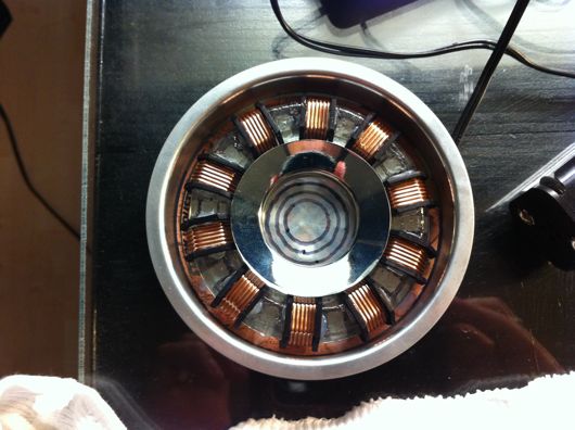
Completed RT Mark II arc reactor

Toward the end (which was the night before the first Halloween party I had to go to, I decided to make that center lens with sanded lexan and hand-drawn concentric circles. The one in the movie had a cool ridged lens like those on a lighthouse lamp. I ran out of time and patience and this is the compromise. :)

On to the steps I took, shall we?

First, I drew up plans. I'm not much of a planner, but something this weird needs some kinda goal. Dr. Stephen Covey says to start with the end in mind. Smart man. I couldn't have winged/wung/wanged this one.
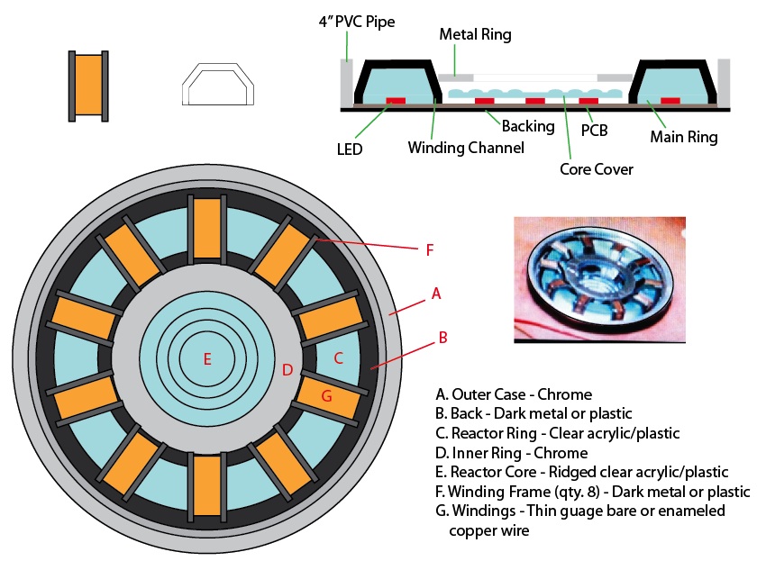
Plans for my arc reactor

I drew the plans to-scale in Adobe Illustrator. I took this sheet with me to Home Depot, Michaels, Target, etc. to find parts to fit. Most of that hunt went well, save for the stupid big clear plastic ring with the copper windings around it in ten places. That's where this turned into a learning experience, as well.

Let's start with the worst part of this build, which, based on my lack of talent and knowledge in electronics, should have been the electronics. It was not. The worst part was that damn plastic ring. I've watched enough Mythbusters and on-line crafting and DIY videos to know that you can "easily" cast your own parts at home. "Easily" is a term I now use sparingly and loosely when it comes to my DIY/maker/tinker projects.

To mold a part, you have to have an original. How hard could it be to make a ring? I can cut wood, sand it, make it pretty darn smooth and shiny and nice. Attempt at making a ring original was done in wood. It sucked. My old, worn out hole saws (big circular drill bits that cut large diameter holes in things) butchered the hard wood I was trying to cut the ring out of. Usually, I can handle a rough cut and can clean up after it. This was beyond reparable. I didn't even bother to take photos. I still have it, though. Lesson learned.

Yucky wood ring attempt

Second attempt was bending acrylic rods. Can you say bubbly? Can you say distorted? Can you say FAIL?

Bending acrylic = Bleh

Third time was a charm. I ran to Michaels and bought Sculpey polymer clay. It's very cool stuff. You make a thing out of it and bake it for 15 minutes at 275° (I recall) and it becomes hard and sandable and carvable and all that jazz. Awesome stuff. I formed the ring as a long rod, first. Gave it its profile shape using some aluminum straight edges and my level, then bent it around to fit the plans I had been carrying around. I trimmed the extra length off and smooshed the ends together and smooth all of it out. It looked rough, but workable. I baked it. I sanded it and shaped it into a pretty darn good first-ever Sculpey part:

Polymer original for reactor main ring

I used a heavy bearing as a sort-of rolling pin to help shape the ring. A razor was handy and the straight edge things were perfect:

Tools of the trade

The next step, at least from what I've been reading, was to layer a bunch of latex over this thing to make a mold from which we will eventually make a clear epoxy resin ring.

Seal around the bottom

Suggestions from a number of experts say that you should glue your part to a non-porous surface and seal the gap under it with clay or something similar. I did. It was a good call, too.

Next, layers and layers of latex are painted over the part until a fairly sturdy but flexible rubbery mold was built up:

Layers of latex

Each layer needs to be dry before the next on goes on. It was tedious, but very cool when finished.

Finished latex mold

Reminder: I suck at casting and mold making. Do not follow my lead. I scraped by on this one. The image above was my second attempt because I ignored some recommendations in the first try. Buh-bye, time. This one shown above, though, was great! But, like the videos will show you on-line, you need a, "mother mold" made of something sturdier to help the latex mold keep its shape. I did that with plaster of Paris:

Plaster of Paris from DAP

You can get a bucket like this one at Michaels for cheap. A few bucks. While the latex mold was still sitting on the original in the pyrex dish, I glopped on the plaster, which I mix slightly thicker than usual to help it stay in the shape I made it:

Completed mother mold

It worked great. It was perfect, but it was good enough to cast resin thingies.

The next step was to carefully follow directions and mix clear epoxy resin with activator and pour that into this mold. That's great, in theory... Following directions, that is. I was interrupted while counting drops of activator and didn't get enough in the resin goop. I also did not sir it vigorously enough and even properly, according to directions I'd watched three or four times on YouTube. Like the silly latex mold thing, I had to do the resin casting twice. Sadly, neither was great. The second attempt was at least workable for this project.

Clear epoxy resin in latex mold

The above photo is of the second casting. Sadly, the mold was slightly gooed up by the first casting. The second was the right ratio of activator and resin and would have been awesome, but the outer surface stayed tacky for a while because it did not fully cure. Luckily, it didn't affect the overall finished product too much. Since the silly prop was going to be under my shirt most of the time, nobody would notice the craptastic casting job I did.

Here is the final part:

Final clear epoxy resin reactor ring

The texture was from me trying to impart a texture with a paper towel. It kinda worked, but mostly didn't. It's OK, though. The ring does a great job of scattering the ridiculously bright blue light from the LEDs in the final product.

The next step was to build the copper windings that are on the main reactor ring (the clear thing above). This seemed like a pretty straightforward process until it came time to actually do it, of course. I ordered some c-channel ABS model railroad strips from Plastruct. They are perfect, but there are 5 tiny parts for each of the 10 locations around the ring. Cutting those little parts was ultra-tedious and highly inaccurate and inconsistent. I had planned to cut the angles and to use model glue to build them ahead of time and then simply stick them onto the ring. Ha! Funny.

So, plan A for the windings was a FAIL. Plan B was to carefully heat the c-channel stuff and to bend it over the ring. FAIL again. It mostly just curled up and got bubbly, even with low heat. Plan C was to cut each side of the winding channels from thick, black cardboard or Sculpey (and then bake the Sculpey). During another of many trips to Michaels, I bought a sheet of photo matt stuff. It was fairly thick, I could cut it with an Exacto, and I could paint it or Sharpie it. This didn't seem horrible, at first. But, it was one of the most tiring and laborious parts of this build. Look at the parts laid out on the cutting mat:

Reactor ring winding channel sides

These were cut from a strip and I used a template drawn in Illustrator for shape them. At this point (in the photo above), they were easy to work on. The next step was the crappy part: Cutting the insides out of them:

Steps in making each of the 20 channel sides

I went through about 4 or 5 Exacto blades cutting these shapes. My hands were killing me by the time I finished. They also had to be painted all black with a Sharpie. This particular cardboard is matte for a photo or painting. It is black on one side only.

Now that the channels were ready to keep the windings in place, it was time to do the actual windings. I purchased two pounds of 22 gauge and 24 gauge bare copper wire for this. The idea had the potential to look awesome and authentic. The first and only true copper winding took about an hour. Forget that racket. Let's think more like a low-budget Hollywood prop make would... Think, think, think... I was up until about 1:30 that night and gave up on a solution. Here is the awful real copper winding:

Yucky real copper winding

The next morning, I came up with the idea that would save me countless hours of carefully wrapping copper wire around a sticky resin ring: Cut small strips of old IDE hard drive ribbon cables and kink them to the profile shape of the ring. Genius, if I do say so myself:

IDE ribbon cable as copper windings

The only thing they ribbon cable bits needed was a nice coat of copper paint. Testors makes a great copper paint, as you can see:

Genuine simulated copper windings

Now, before I move past the windings, how they're held onto the ring is another bit of niftyism: I drilled holes through the ring so that I could take some of that two pounds of bare copper wire and stick it through the ends of the ribbon cable and lock them in place:

Fastening the windings onto the ring

Also, while the outer surface of the ring was tacky, thanks to my complete lack of casting skizillz, I carefully wrapped the edges of the ring with tin foil, shiny side inward to help bounce the blue light around more inside the resin:

Tin foil reflector things

The only thing left on this whole copper winding fiasco was to glue the channel sides onto the ring along each side of each winding:

Winding channel sides glued on

Since I was running out of time, I didn't do this as cleanly as I would have liked. Upon close inspection, it looks atrocious. But, on shelf or under a shirt, nobody is none the wiser more none... Er... Yes. How about that copper paint?!

Earlier in the build process, I had to make the outer ring. In the movie, this was the container embedded in Tony's chest that held the reactor. I used ABS plastic pipe, cut a 1/2-inch slice with the band saw, and painted it with chrome(-esque) paint:

Outer ring from 3-inch pipe

The center chrome ring was a drain thing I found at Home Depot:

Drain thing from Home Depot

I cut the threading off and ground down the flange to the proper diameter for the center of the reactor.

The last hurdle was how to wear the silly reactor. My wife, in a flash of brilliance, suggest we Velcro the thing to my undershirt. Well, prior to that, I hadn't thought of wearing a shirt under my shirt. The final reactor had black felt on its back to make it more comfortable against my chest. To accommodate the Velcro idea, I just hot-glued the fluffy half of some Velcro pads to the back of the reactor:

Fluffy side of Velcro on back of reactor

Then, I sewed the hooky side of the Velcro pads to the front of a wife-beater shirt:

Hooky Velcro pads on shirt

Completed kit, Velcro on shirt

I'll be wearing the wife-beater under a thin white long-sleeve casual shirt. The reactor is still incredibly bright under even a dark brown t-shirt:

Clearly visible, even with a flash and dark brown shirt

Here is the reactor turned on:

RT Mark II arc reactor replica powered up

It's silly how bright it is. Should make for great conversation at the parties.