Starting the next generation Fitbit Cheat-O-Matic, but changing the name, switching to proper high-end bearings, and make a sturdier base and cam follower mechanism. Should be slick if everything fits nicely and plays nicely.
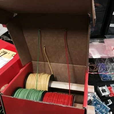
If you're like me, and I know I am, you have spools of wire or solder sitting around. I generally put mine in the cabinet above my desk. Lately, with more projects going on, I find myself pulling them down out of the cabinet constantly. I had a collection of the most used spools sitting on the workbench cluttering it up. Well, no more, I say! Here's how I organized them and made it easier to pull pieces from them quickly.
I LOVE my iPad 2. To protect it, I HIGHLY recommend the DODOcase (http://www.dodocase.com/products/dodocase-for-ipad2). My only complaint would be the lack of a magnet in the case to activate/deactivate the iPad through its little magnetic sensor, which is used by other cases, like the foldy-flippy one from Apple (http://www.apple.com/ipad/smart-cover/).
What to do? Hack, of course! But, first, I emailed the DODOcase peeps and suggested the feature to them and even sent them links to my source of delicious rare earth magnets, K & J Magnetics (http://www.kjmagnetics.com/). There are thin little rectangular magnets that can easily be embedded into the cardboard cover underneath the backing.
For now, my magnet sits on top of the inside cover:
Here is a close-up:
When I have a spare couple of minutes, I'll whip out the X-acto knife and make a neat little compartment for it under the blue liner of the cover.
The Short Attention Span version: I ripped apart a cheap remote controlled car and repurposed most of the parts into a self-balancing robot based on the Domo character because I thought one of the partners of the company I work for would enjoy it, as he seems to enjoy Domo stuff. I got the idea from a coworker who suggested I build this for the Domo partner.
The idea is not original to me. I was sent a link to Instructables.com that showed one in action. I didn't follow the directions, so the engineering is my own brew. But, I will say, that's an ingenius way to make an upright, two-wheeled roboto-doo-dad.
Here is the YouTube video of the robot in action:
So, the first thing I did was destory this car (or it was a close cousin):
I took out the main circuit board from the car and the circuit board from the remote.
I figured out which wires ran which motor. One set ran the drive motor to make the car go zoom. The other set ran a motor that simply turned the steering all the way to the left or all the way to the right. No in-between steering on this one. The front wheels self-centered thanks to a little spring. BUT, we had two motors controllable by two rocker buttons on a remote and that's all we needed.
I ordered some little rocker switches, a battery, and a plastic project box into which I could mount the remote stuff. I wound up trimming the circuit board down and resoldering the leads to the buttons so that it would fit snuggly in the project box.
I made the base and wheels (shown later on) out of some poplar I had lying around. I guesstimated all the sizes and dimensions, basing them around the way things kinda fit together on the board I used for the base. I ordered some geared down DC motors from AllElectronics.com. The wheels needed to not spin too quickly or Domo would constantly slam his head down on the ground. Gearing down the 6V supplied by the circuit was simple and cheap.
I cut strips of rubber gloves and lined the copper motor brackets with them. This did a nice job of preventing the motors from twisting themselves when starting up. At the point I built the base of the bot, I hadn't purchased the bike inner tube that I used to cover the wheels to make them more grippy-tactic, otherwise I would have used that material.
Next, I needed to make wheels that were as circular as I could get them so that Domo didn't roll with a limp. I searched the web for easy jigs to cut circles with bandsaws. The crazy-simplest one I found was just a brad nail in the dead center of the circle to cut and a board below on which the piece being cut could rotate. Place an edge of the circle up against the blade and SLOWLY start rotating the piece. I say SLOWLY because pushing too quickly makes the blade run off-course. I have new round scraps of wood to prove it.
Notice the lower piece right behind the blade. The closer that bottom piece is to the blade, the better it supports the piece being cut. The cut needs to start at the edge of the circle because we're only going to rotate the piece being cut. If you don't scribe your circle as perfectly as you can and you don't put that rotation point as dead-center as possible, it won't be a beautiful circle when it's completed.
At first, I only used a single motor bracket. That gave the robot a sloppy angle on the wheels, so I added a second bracket to help sturdy up the axles. The wheels were 1/4-inch at first. I switched those out with 1/2-inch to add a little more stability to the wheels. As you can see in this photo, I simply hot-glued the main board in between the batteries and the right side motor.
I cut a notch and mounted the power switch facing downward, initially. That was painful and dumb. So I flipped it over. Why? First time the bot made a turning start, he switched himself off. Duh.
Now, as mentioned above, the whole idea behind this thing staying upright on its own is for it to have a heavy butt. With four D-cells and a bunch of metal bars and wheel balancing weights, you'd think that would be enough to counter that wire frame. You'd be wrong about that. I had to snip out a bunch of that wire to lighten the load to make him more bottom-heavy.
To firmly attach the skeleton to the butt, I left plenty of extra pokey wires on the bottom edge of the skeleton. I then drilled holes in the base and pulled the skeleton down through them. I bent the wires outward and then ground them down. In fact, EVERY STEEL wire sticking out needed to be ground down. I know have lots of little holes in my hands and arms, thanks to that incredibly pointy steel wire.
I bent the shape of the skeleton on my table saw. I used a metal straight edge to push each bend down into the miter slots on the steel table of the saw. It worked great! Since I always do my own stunts, climbing up on the table saw wasn't that big of a deal.
For the bot to stay upright, as mentioned above, weight was key. Besides the big batteries, I needed some more weight below, so I picked up some joist repair bars at Home Depot. They're heavy and they have nice countersunk screw holes in them. I mounted four of them to the base and then used some car wheel balancing 0.5 gram weights I got free from a very nice guy at Pep Boys Auto Parts. I used the little weights to get the bot balanced and vertically straight. It's incredibly heavy, but stable.
Another thing I think I mentioned before was the need to lose some weight up top. I cut some strategic holes into the body to lighten the load. It worked perfectly.
With the help of a little construction paper and a glue stick, the body is complete. At this point, as you can see in the photo, the body construction paper isn't bent inward down near the base. I eventually did that and tacked the edges every inch or so with some hot glue for good measure. I also put construction paper on the wheels to add some nice finish to the thing.
The power switch and the batteries are accessible through a flap in Domo's butt. It sometimes flaps in the breeze while he's running around, like the tails of a tuxedo coat.
I got a handful of slick little rocker switches to run each motor forward or backward. I did some minor butchering on the holes underneath the flanges of the switches. What does one expect for a free robot skinned in construction paper? The red LED is the original from the RC car remote. The antenna was a piece of wire I had on my bench. To change the 9-volt battery, you just unscrew the four screws on the bottom of the box. Easy.
I used my trusty little label maker and put some stickers on the buttons to aid in its use.
To steer Domo around, you drive him like a tank: Push both buttons forward to move forward in a straight line. Push just one to make a wider turn. Push both buttons opposite each other to spin him in place. Push both buttons back and he goes straight back.
Dave, the guy I gave the bot to, has a dog. The dog doesn't like the bot. It is funny to watch, though.
Needs more shine! The light bulb inside is medium OK in its ability to attract insects and people with ADD, but I wanted a little better (not too much, though). I also wanted signage. This is a super-simple project that anyone with even questionable soldering skills can pull off. Plus, there is enough room behind the red part of the button to put most any LED you like.
Eet's Oh-Kay. What's more fun than a big-honkin' red button?? It could wind up as a History Eraser button like on the 90's cartoon Ren & Stimpy. Maybe a self-destruct button? I'm going to make something similar to the button from the movie The Box. Nice wooden case, flip-open lid, big lettering that reads, "DO NOT PRESS" and pulsing backlighting. How can you NOT press a button like that? When the button is pressed, it will play Daffy Duck going nuts.
Here is the original light bulb lit by 12 volts AC:
It's OK and looked decent behind the red dome, but it draws a bit of power and it's old fashioned and not as neato as LEDs.
We start by flipping over the button and checking out what we have to work with.
We need to take this thing apart to the point that we have all the pieces sitting on the desk, ready to be upgraded. The switch and light assembly twists to unlock and then pulls out of the center of the button.
Next, pull out the lightbulb from the assembly. It simply pulls out. Just tug on it, maybe wiggle it a bit, and it will come out eventually.
Unscrew the big white plastic nut from the back of the button to release the main part of the dome button from the bigger black base thing. You'll be left with the basic parts and you can display them neatly like I did:
To release the top red part of the button, the dome, from the whole thing, you need to squeeze the little white tabs inside the center of the button where the switch and light assembly was.
Once that red dome part of the button is loose from the black base, you can pry the red off the white with a little screwdriver or other similar implement in order to get to the pulp and juice of the fruit. What?
Now we have access to the disc inside the red dome to which we can affix signage.
I took a quick measurement of the white disc and fired up Adobe Illustrator (which I also use to create my circuit board designs) to make the appropriate sticker. I printed the words on full-sheet sticky-backed laser printer paper, available at many places. If you can't find it, this project is probably over your head.
For this hack... I mean, upgrade, we're using my favorite little SMD LEDs from SuperBrightLEDs.com, or pick your favorite supply source. They have three little white LEDs in a single, easy-to-solder surface-mount package. I've used these many times for projects like the Iron Man arc reactor, the LED reading lamp, and a new project about to be posted (you'll have to check back to see it).
Two things happened in this next step and I forgot to photograph the process, but I took a strip of IDE cable and peeled a section of three wires from it. I then placed that three-conductor cable and placed it inside the perimeter of the white part of the button where the light bulb used to shine through. I marked it to the length of the inner circumference of the white thing. I then divided that by 3 and chopped it in the two spot and trimmed back the insulation on each of the ends of the cables. I then soldered each of the three LEDs in each of the three SMD LED packages in series. Basically, I just daisy-chained the LED packages together. At one end, I soldered a single, 22 gauge wire to the cathodes of the LED package. On the other end, I soldered another 22 gauge wire to the anodes of the LED package. Look at the second photo of the interior of the dome below.
I lined the inside of the dome with sticky-backed foil, which I picked up from Home Depot. It's in the plumbing and heating section and they use it to seal and for reflective insulation, I think. All I know and care about is that it makes a great reflective surface for scattering light. I used it in the Man Cave lighting upgrade and 12 VAC power supply project.
Here is a closer shot of the LEDs and the IDE cable:
The foil tape holds everything in place. The positive and negative leads then are routed out through the hole in the center where the light bulb used to be located.
As always, I marked the leads for positive and negative.
And here is the main part of the button put back together:
Now, put the dome assembly back into the black holder and put the spring back:
Next, we need to prepare the switch thing a bit. The brass clips inside the switch holder need to be removed. We don't need them at all. You could solder the leads from the LEDs to the brass thingy, but I didn't. Use a small screwdriver again to pry the side away from the switch. There is a notch that the plastic snaps into on the switch. Once you pry that away, the plastic holder will slide off the switch easily.
Next, remove the brass clips. They will be bent pretty well in the process. Doesn't matter. We don't need them.
Route the leads through the plastic switch holder and twist it back into the button.
Next, route the leads out the sides of the holder so that the switch will snap back into place.
Connect the leads to your 12-volt DC power supply with a limiting resistor (depends on your LED specs) and it should light right up!
A coworker walked up to my desk and handed me this USB-controlled Nerf-esque dart launcher thing from Think Geek because it wasn't working. If it was dead, I thought I'd at least get a number of little motors and gears and whatnot. I took it home, removed all the screws and completely dismantled it to see how it works. It's ingenious inside. I won't get into it, but it's pretty cool.
I decided to put it back together, sans its main circuit board. Everything appeared to work, as far as I could tell. I figured out that the darts were gripping the nozzles on the barrel of the gun to tightly, so I jammed a needle nose pliers in the back of the dart and spread 'em open a little more. That fixed it.
Next question: What to do with this thing. I removed the main board and had all the wires for the motors and the switches hanging out the hole where the USB cable used to be. Man Cave Security called and said we needed some kinda defensive system to connect to the new [fake] talking alarm pad. I'll post the rest of the photos of the finished weapon when it's completed. In the meantime, here is the reassembled launcher with a new 12-pin header soldered to the wires for easy breadboarding:
Here is a close-up of the header hanging out the back of this thing:
So, like I said, once I get some more work completed on this bad boy, I'll post the fun photos.
I recently rebuilt the lighting in my office because the crappy 12-volt strung lighting from Ikea that the previous owner installed was insufficient for working comfortably in my Man Cave™. Here's the NEW lighting above the sound-proffed barn door window shade things:
With the intensity of the photo cranked down a bit, you can see the simple valence I made out of pre-primered pine trim board:
The old lighting was 12VAC wire cable lighting with halogen lights. You seem the at Ikea. Two steel cable strung between two walls and the halogen lights hang between the wires at regular intervals. It's really cool, but it isn't very bright and the light is very yellow. I like daylight-ish fluorescent lighting, so that's what I bought to replace the old stuff.
Now, on to the real story: I salvaged the wall wart transformer/power supply for the 12VAC lighting and made a simple 12VAC power supply out of it. Not sure what I'll use that for, yet, but it was fun and I feel like I saved the landfill from containing weird metal and plastic parts.
I removed the pushbutton fuse reset thing and replaced it with a neon lamp power switch with a fuse reset feature and then cut a notch in the base of it to hold a strain-relief thing for a power cable from an old VCR I torn down. Then I put a wood base on the back and screwed in to together and sanded it for a nice finish. I haven't painted the edges black, yet. I also need to put little rubber footies on it to keep it from sliding around on the glass top of my electronics workbench.
Here are the photos:
Completed power supply with power cord and switch.
Bottom is screwed into four holes built into case of wall wart. I wrote the specifications from the sticker on the transformer inside so that I would not forget how this could catch fire or trip a fuse.
I realized after I put it all together and tested the power that the replacement power switch might not trip at the same power draw as the old pushbutton. So, when I laid a big piece of copper wire across the terminals, it sparked and never did trip the switch OR the circuit breaker for the garage workbench. That's probably a fire hazard, but I'll usually have a good quality surge strip (or two) AND a house circuit breaker between my mishaps and the neighborhood power lines.
In my UME Mark II's (UME = "Useless Machine Ever"), originally I would program an Atmel AVR microcontroller to turn an RC servo forward and backward using timed pulses like you're supposed to. But, when you want to build many machines, microcontrollers are not the way to go. Simple polarity-changing circuits are the way to go. But, you still want the RPMs of a servo without the hassle of the pulsing control. So, you hack the servo and make it a geared motor. Easy! Here's how...
Grab yourself one o' them thar RC servos for a good price at your local hobby shop or on-line. They look so innocent. If you listen, they make a whimpering sound because they know that phillips head screwdriver in your hand is there for kicks.
I hope that my lack of knowledge in all that I do is entertaining and not a hinderance in the usefulness of these posts. :) So, that said, look at the above picture. I took off the star-shaped armature thingie.
Unscrew the screws in the bottom of the case of the servo-soon-to-be-geared-motor.
Remove the cover on the bottom of the servo. You'll see nifty circuitry and the spots where the three wires are soldered to the board.
Carefully remove the top of the servo that contains the gears and pins and lubricating goo. I bold the word, "carefully" because you need to put this all back in the way it came out. If you can't get it all back together, you will have a nice pile of gears, pins, circuitry, a plastic case, some wire, and a neato DC motor. Take pictures if these don't cut mustard. They can help back track the destruction and make it reversible.
Shimmy the neato circuitry and motor guts out of the plastic case. The potentiometer (black thing standing on thick leads opposite the motor) is used by the circuitry to indicate where the shaft is positioned at any given moment. Once the hack is complete, it will be unused. I'll give you some options for it later on.
I used my ACMG robot (aligator clip magnifying glass) to hold the guts while I worked. Desolder the three wires from the board. Remember not to heat the stuff you work on with the soldering iron for too long. That heat can travel to components that don't like warm weather and can cause severe rash or sunburn or death.
Solder the red and black wires to the motor leads. Once you do this, the servo is simply an inexpensive geared motor. The robot makes this very easy to do. You can use a wife, girlfriend, son, daughter, or even an uncle to hold the work, but they're nowhere near as steady as a the alligator clips.
Wires soldered. Route them between the pokey little component leads sticking out of the bottom of the neato circuit board because there isn't much room between the PCB and the case cover and the wires have to travel across the board to the hole in the case. I like the path I chose. It looks like a... Well, it doesn't look like anything, but you can pretend.
View of the servo... Er, almost-a-geared-motor (now) looking at the underside of the top of the servo (with the gears) and the top of the main body (at right). The bearings on the black gear are tiny and cool. That black gear has a little nub on it that acts as a stop at one of two positions 180 degrees from each other in the rotation of that shaft. We need that snipped off and trimmed.
See the nub? It's what I'm holding onto with the wire cutters. You need to trim that down flush with the shaft and with the face of the gear (the part of the gear parallel to the back side of the wire cutters in this photo). That will prevent the gear from stopping against the stops that are built into the case of the servo.
Look on the right side of the gear, just below the bearings on the rear of the face of the gear. Make sure there are not bits left behind or you will hear clicking as those remnants click past the stops in the gear box. I suppose you could clip the stops, as well. But, you can see in this photo that I have a little bit of trimming to do, yet.
Use your new geared motor as you wish. I learned to circumvent the circuitry on these from various posts on the IntarWebs. It's not hard at all. If you screw up, the servos I found locally at the hobby shop were only about $12, so it isn't the end of the world if you fubar one. In the photo above, you can see the unfinished tops and "robotic arms" from one of the Useless Machines (see post on my site about this device).
This is one of the first "major" projects I built that involved electricity and electronics. This project makes it super-simple for me to manage my expensive (for me) cigar collection with minimal effort. It uses a 6-bottle wine fridge, some custom-cut Spanish cedar, and a Cigar Oasis XL electronic humidor humidifier.
The fridge was about $99 on-line (I may have gotten it at Wal-mart's website, I can't remember). The Cigar Oasis was about $90 on-line. The Spanish cedar was the expensive part. I think I spent about $160 for a 6' piece of uncut and unfinished wood. I had to have the people at Woodworker's Source (Phoenix area, near my home) rip the big plank down to nice and thin planks with which I could line the fridge. The cutting part was about as much as the plank of cedar.
I kinda rushed this project, as you can see. The shelves are not completely level and don't fit perfectly. Most of my time was spent measuring and shaping the pieces so that they would fit without needing glue or fasteners. It turned out well enough to do the job.
The electronics weren't too tough. It was my first project that involved busting open a device that used wall power. That was unnerving. But, it isn't rocket science. I just opened up the back of the fridge, found where the power supply fed the electronics of the fridge at ~5V and tapped the power cord of the Cigar Oasis into that line. The Cigar Oasis doesn't draw a lot of power, so it seemed the power supply wouldn't mind. Er, at least, in the two or three years it's been running in my Man Cave™, it hasn't quit or caught fire. ;)
Like I just said, it's been running for about two or three years and I've filled the Cigar Oasis maybe twice. Other than that, I haven't touched the humidor for maintenance, only to select cigars to enjoy. The fridge keeps the temperature at 70 degrees fahrenheit and the Cigar Oasis keeps the humidity inside the fridge at about 70%.
The photo above is the coolidor after about two or three years. I've loaded and unloaded lots o' cigars. The little readouts on the Cigar Oasis and the little electronic hygrometer don't ever match. The cigars smoke perfectly, so the "63%" showing on the gadget there is low because, when you open a humidor in Arizona, the humidity escapes rapidly... Because we're in a desert. But, when it reads about 65% upwards to %68, the cigars are happiest in my experience. To get the optimum humidity, I have to keep the Oasis set at about 68%.
This project is easy to do. If you're a cigar geek, I highly recommend taking a little time to build a humidor that can manage itself. Set and forget. It's awesome.